Processing Plant

a processing plant and processing technology, applied in the direction of metal-working holders, supports, positioning apparatuses, etc., can solve the problem of reducing the space requirement of the entire processing plant, and achieve the effect of improving the logistics of components

Inactive Publication Date: 2008-11-06
KUKA SYSTEMS
View PDF15 Cites 22 Cited by
  • Summary
  • Abstract
  • Description
  • Claims
  • Application Information

AI Technical Summary

Benefits of technology

[0004]The object of the present invention is to improve the component logistics.

Problems solved by technology

The space requirement for the entire machining plant decreases as a result.

Method used


Image

  • Processing Plant
  • Processing Plant
  • Processing Plant

Examples


Embodiment Construction

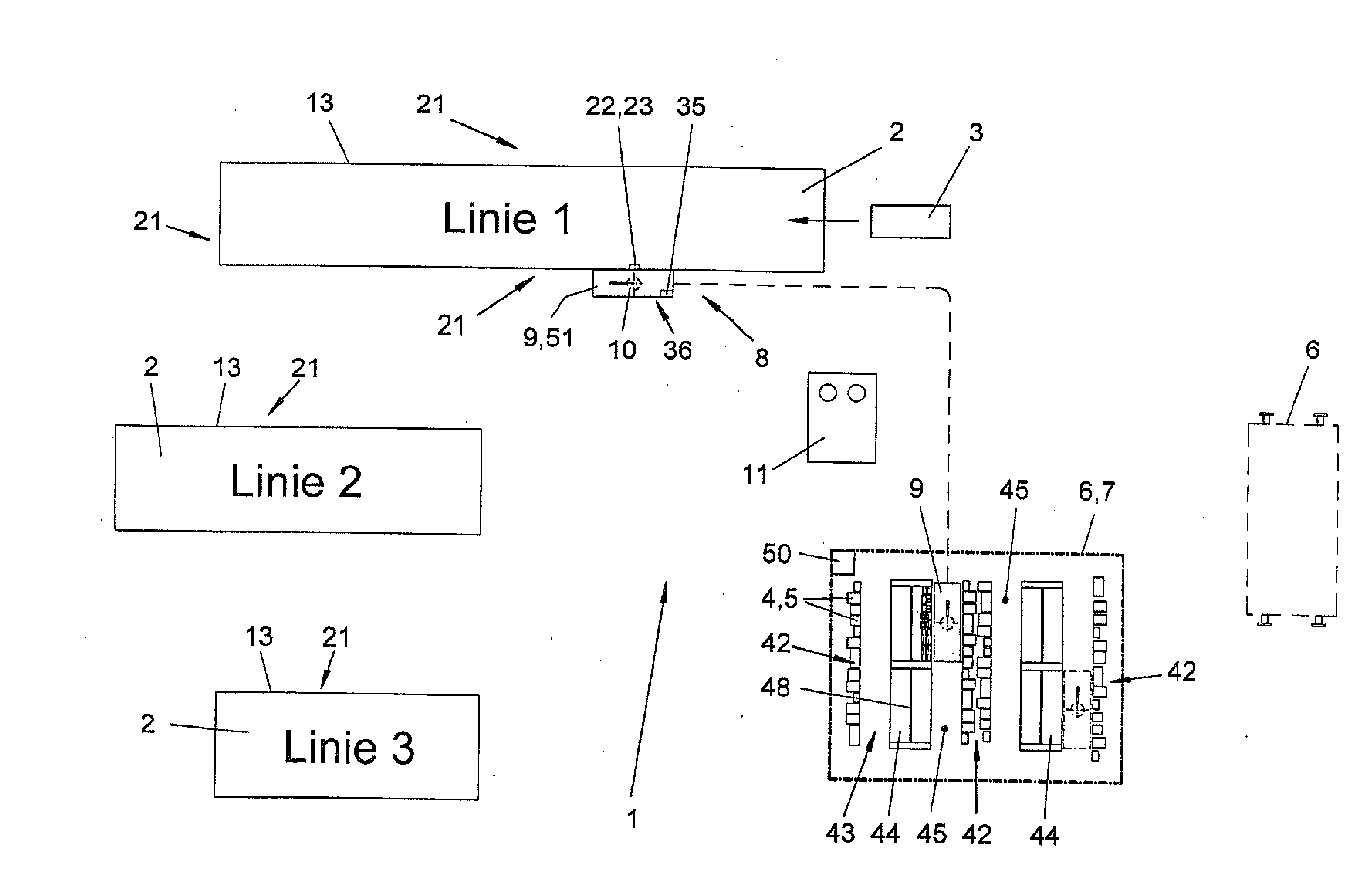
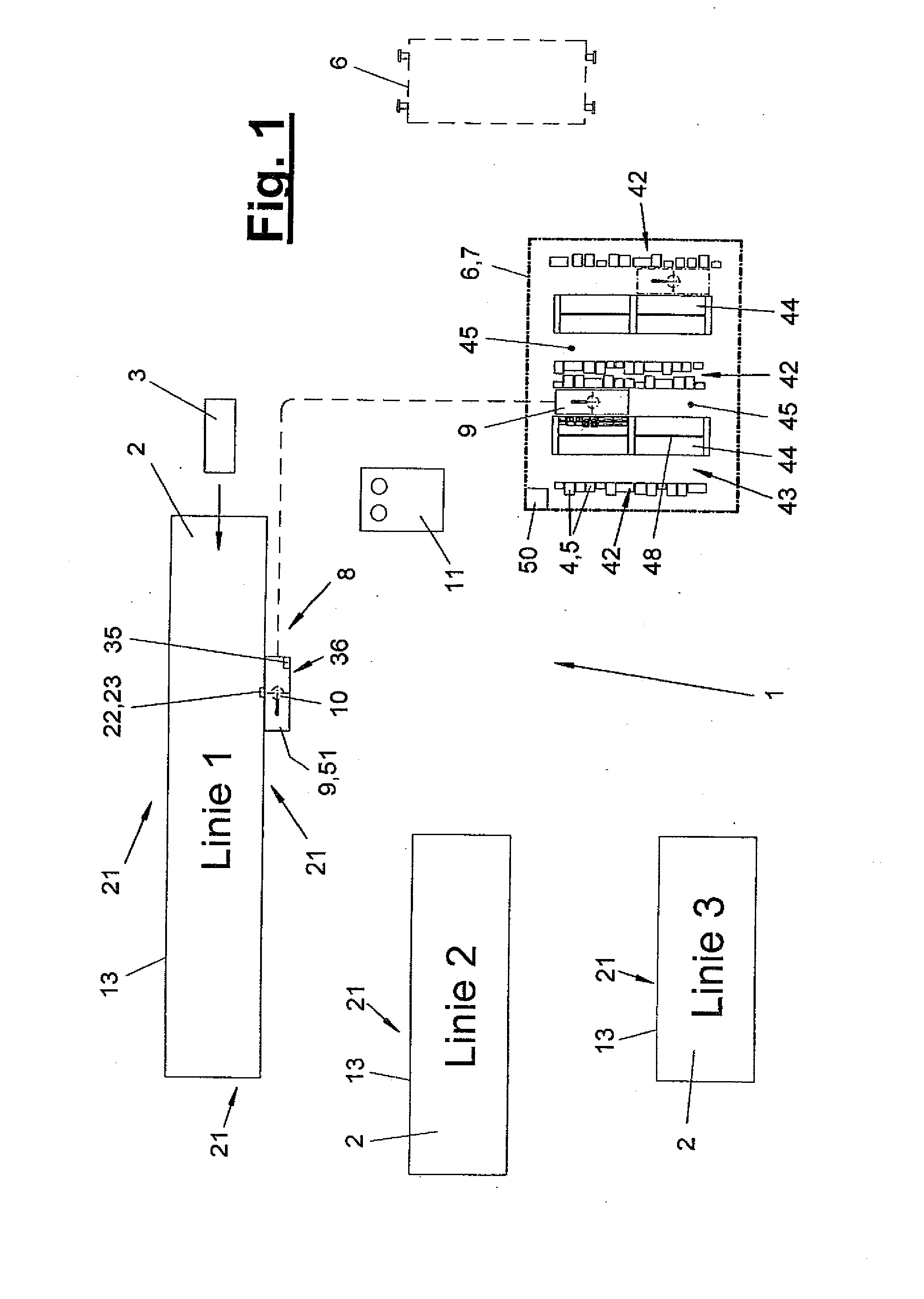
[0027]Referring to the drawings in particular, The present invention pertains to a component logistics for a machining plant 1) with the device and process technology belonging to it.

[0028]FIG. 1 shows a schematic top view of a machining plant 1, which has one or more machining stations 2, which are designated here as lines 1, 2 and 3. The machining plant 1 has, furthermore, at least one readiness position 6 for components 4, 5, which is designed, e.g., as a component center 7. As an alternative or in addition, another readiness position 6 may be present, which may be, e.g., a transport vehicle indicated by broken line, especially a railroad car, a truck or the like, in which components 4, 5 are brought precommissioned into the machining plant 1 or are made ready here. The readiness position 6 is located outside of and optionally separated in space from the machining stations 2. A readiness position 6 can service a plurality of machining stations 2.

[0029]The machining plant 1 contai...


PUM

PropertyMeasurementUnit
work areaaaaaaaaaaa
areaaaaaaaaaaa
widthaaaaaaaaaa

Abstract

A machining or processing plant (1) is provided including one or several machining stations (2) that are surrounded by a protective partition (13) and are supplied with components (4, 5) from at least one external supply (6) by a feeding mechanism (8). The feeding mechanism (8) is provided with one or several distribution vehicles (9) which can be moved between the supply (6) and the processing stations (2). The distribution vehicles (9) are equipped with a multi-shaft manipulator (10) and a device (36) for surmounting the protective partitions (13). The distribution vehicles (9) are also equipped with one or several receptacles (30) for component supports (24, 25).

Description

CROSS REFERENCE TO RELATED APPLICATIONS[0001]This application is a United States National Phase application of International Application PCT / EP2006 / 009130 and claims the benefit of priority under 35 U.S.C. § 119 of German Patent Application DE 20 2005 015 118.1 filed Sep. 23, 2005, the entire contents of which are incorporated herein by reference.FIELD OF THE INVENTION[0002]The present invention pertains to a machining plant with at least one machining station with a protective enclosure surrounding same, with at least one readiness position and with a feeding means for feeding components.BACKGROUND OF THE INVENTION[0003]Such a machining plant is known from practice. It contains one or more machining stations, which are surrounded by a protective enclosure, e.g., a fence, which prevents free access to the work area within the machining station for persons for safety reasons. One or more special accesses with special securing means, which switch off the machining devices arranged in ...

Claims


Application Information

Patent Timeline
Patent Type & Authority Applications(United States)
IPC IPC(8): B23Q7/00B23Q7/04
CPCB23P19/001B23P21/004B25J5/007Y10T29/51Y10T483/165Y10T29/5136Y10T483/115B62D65/18
Inventor STURM, THOMAS
Owner KUKA SYSTEMS
Why Eureka
Try Eureka