Surgical Cutting Guide

a cutting guide and surgical technology, applied in the field of surgical tools, can solve the problems of inadvertent injury or cutting of other tissues, slipping of surgical instruments, deflecting, etc., and affecting the stability of ligaments,

Active Publication Date: 2008-11-06
CONFORMIS
View PDF100 Cites 491 Cited by
  • Summary
  • Abstract
  • Description
  • Claims
  • Application Information

AI Technical Summary

Benefits of technology

[0018]In further related embodiments of the invention, the stop may protect one or more tibial spines. The guide or guide aperture may direct movement of the surgical instrument towards the tibial spine, wherein the stop keeps the surgical instrument clear of the tibial spine. The guide or guide aperture may direct movement of a saw and / or blade. The surgical cutting guide may be used in a knee, a hip, an ankle, a foot, a shoulder, an elbow, a wrist, a hand, a spine, a vertebral endplate, a skull, a pedicle, a posterior element, or a spinous process. The surface may have a plurality of concavities and / or a plurality of convexities. The stop may be perpendicular to a cut plane defined by the at least one of a guide and a guide aperture.
[0019]In accordance with another embodiment of the invention, a surgical tool for a knee joint includes a portion that is a mirror image of a joint, a spine, and / or a structure adjacent to a joint or a spine. The surgical tool further includes a guide or a guide aperture that directs movement of a surgical instrument along a predetermined path. A stop inhibits the surgical instrument from deviating from the predetermined path, wherein said stop protects a tibial spine.

Problems solved by technology

However, sometimes a surgical instrument may slip, be deflected, or stray from its intended cutting path.
When a surgical instrument strays from its indented cutting path, it may inadvertently injure or cut other tissues.
However, if the surgeon accidentally misdirects the instrument or if the instrument is deflected from its intended path, the blade path may extend into the tibial spines or other local tissues.
This unintended cut of the tibial spines may result in the loss of ligament stability.
Deviation of the surgical instrument from its intended cutting path may also have harmful effects when performing surgical interventions in other parts of the body.
For example, in the spine, deviation of a surgical instrument may result in neural damage or damage to bony or disc structures.
In the hip, deviation of an instrument from the cutting path may potentially result in neurovascular damage or damage to bony and ligamentous structures.
In a shoulder, deviation of the instrument path may potentially result in neurovascular or muscular damage.
Deviation from the cutting path may also lead to other unintended consequences.
For example, failure to follow a cutting path may later result in misalignment or poor positioning of an implant.
A poor fit for an implant may result in complete failure of the implant or other complications.

Method used


Image

  • Surgical Cutting Guide
  • Surgical Cutting Guide
  • Surgical Cutting Guide

Examples


Embodiment Construction

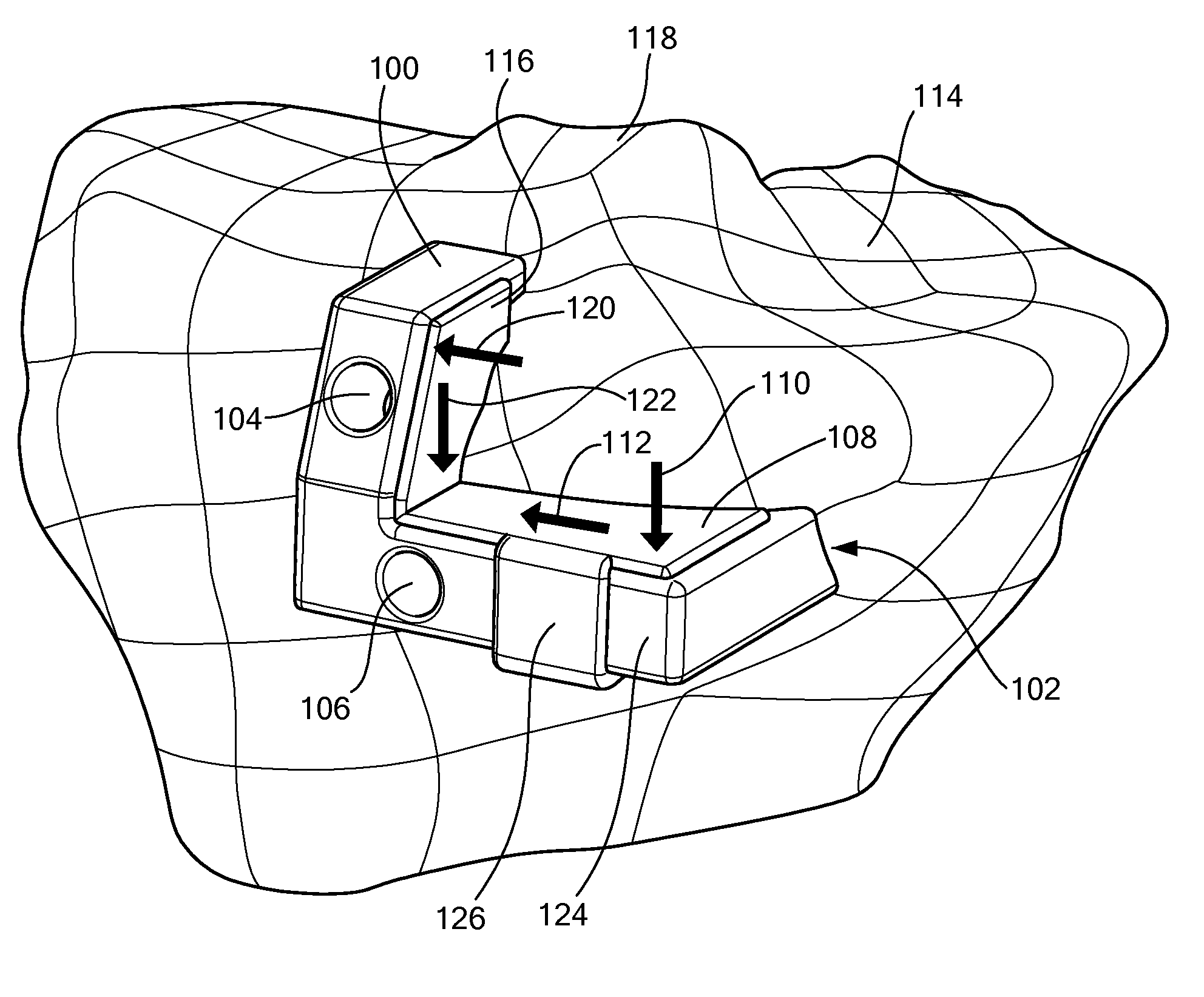
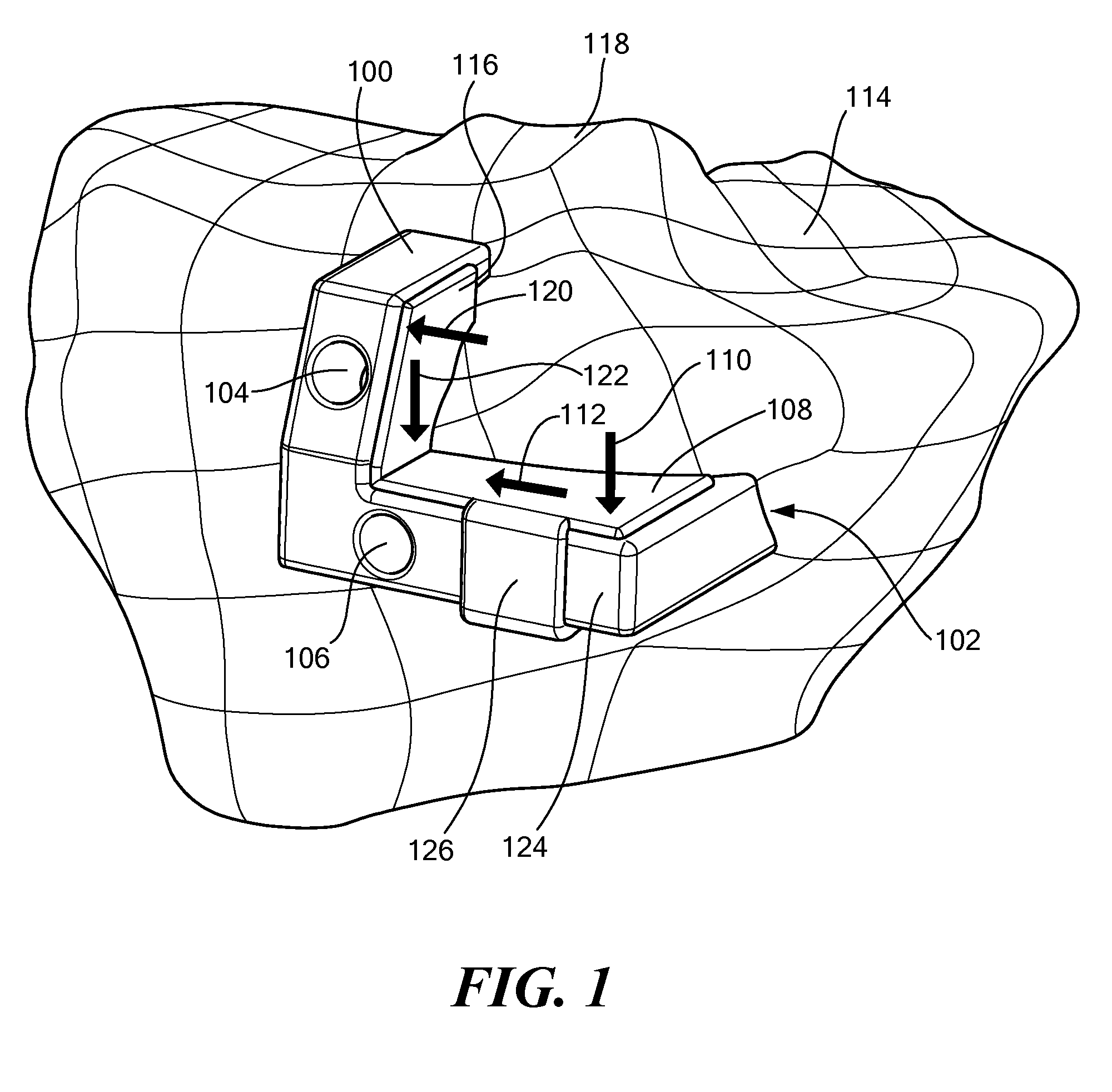
[0056]Illustrative embodiments of the present invention are directed to a patient specific surgical cutting guide. FIG. 1 is an isometric view of a patient specific surgical cutting guide 100, in accordance with one embodiment of the invention. More particularly, the exemplary surgical cutting guide 100 shown in FIG. 1 is a patient specific cutting guide (also referred to in the art as a jig or template) that may be used, for example, in performing a knee arthroplasty. In other embodiments, the surgical guide 100 may be used in performing operations elsewhere in the body, such as a joint, a hip, an ankle, a foot, a shoulder, an elbow, a wrist, a hand, a spine, a vertebral endplate, a skull, a pedicle, a posterior element, and / or a spinous process.

[0057]The surgical cutting guide 100 includes a contact surface 102 that conforms to at least a portion of a surface of a biological tissue to be treated or the structures adjacent to the tissue, as described in U.S. application Ser. No. 11...


PUM


Abstract

The present invention is directed to a surgical cutting guide for guiding a surgical instrument along a cutting path located on a biological tissue. The surgical guide includes a contact surface that conforms to a surface associated with the tissue and at least one guide for restricting movement of a surgical instrument in a first direction and for allowing the movement of the surgical instrument in a second direction along a cutting path across the surface of the tissue. The guide further contains a stop for restricting movement of the surgical instrument in the second direction along the cutting path. The stop is based at least, in part, on patient specific information.

Description

CROSS REFERENCE TO RELATED APPLICATIONS[0001]The present application claims the benefit of U.S. Application Ser. No. 60 / 943,726, entitled “SURGICAL CUTTING GUIDE” filed Jun. 13, 2007, which application is incorporated herein by reference in its entirety.[0002]The present application is also a continuation-in-part of U.S. application Ser. No. 11 / 671,745 entitled “PATIENT SELECTABLE JOINT ARTHROPLASTY DEVICES AND SURGICAL TOOLS” filed Feb. 6, 2007, which in turn claims the benefit of: U.S. Application Ser. No. 60 / 765,592 entitled “SURGICAL TOOLS FOR PERFORMING JOINT ARTHROPLASTY” filed Feb. 6, 2006; U.S. Application Ser. No. 60 / 785,168 entitled “SURGICAL TOOLS FOR PERFORMING JOINT ARTHROPLASTY” filed Mar. 23, 2006; and U.S. Application Ser. No. 60 / 788,339 entitled “SURGICAL TOOLS FOR PERFORMING JOINT ARTHROPLASTY” filed Mar. 31, 2006.[0003]U.S. application Ser. No. 11 / 671,745 is also a continuation-in-part of U.S. application Ser. No. 11 / 002,573 entitled “SURGICAL TOOLS FACILITATING I...

Claims


Application Information

Patent Timeline
Patent Type & Authority Applications(United States)
IPC IPC(8): A61B17/56
CPCA61B5/103A61B5/4528A61B17/15A61B17/157A61B2019/304A61B19/50A61B2017/00526A61B2019/303A61B17/1764A61B2090/033A61B2090/034A61B34/10
Inventor LANG, PHILIPPFITZ, WOLFGANGSTEINES, DANIELBOJARSKI, RAYMOND A.
Owner CONFORMIS
Why Eureka
Try Eureka