Balancing the power of two turboshaft engines of an aircraft

a turboshaft engine and aircraft technology, applied in the direction of instruments, navigation instruments, lighting and heating apparatus, etc., can solve the problems of limiting the performance of the engine, unable to optimize the engine performance, and unable to align the piloting parameters of the engine,

Active Publication Date: 2008-11-06
EUROCOPTER
View PDF6 Cites 42 Cited by
  • Summary
  • Abstract
  • Description
  • Claims
  • Application Information

AI Technical Summary

Benefits of technology

[0029]e) accelerating the engine having the greater power margin in order to bring the first and second engines into power balance, minimizing the primary difference between the first and second power margins to as great an extent as possible, and optionally decelerating the engine having the smaller power margin.
[0047]Similarly, the control means preferably monitors a second secondary difference between a first torque from the first engine and a second torque from the second engine in order to prevent said second secondary difference exceeding a second predetermined threshold.

Problems solved by technology

Aligning the piloting parameters of the engines does not guarantee that their powers will be in balance, since the engines might be operating in significantly different manners.
Balancing on those lines is effective but reveals limitations.
Unfortunately, experience shows that depending on flying conditions, the surveillance parameter that is the most pertinent for achieving balance differs.
Secondly, that principle does not enable engine performance to be optimized.
For example, it can happen that maximum power is not reached on the two engines when piloting as a function of torque limitation.
Finally, that principle for balancing appears to be inappropriate if the piloting parameter is the temperature T45 at which gas is ejected or is torque Cm.
The relationship associating torque and temperature varies as an engine ages, so it becomes difficult to balance two engines if they do not present the same degree of aging.

Method used


Image

  • Balancing the power of two turboshaft engines of an aircraft

Examples


first embodiment

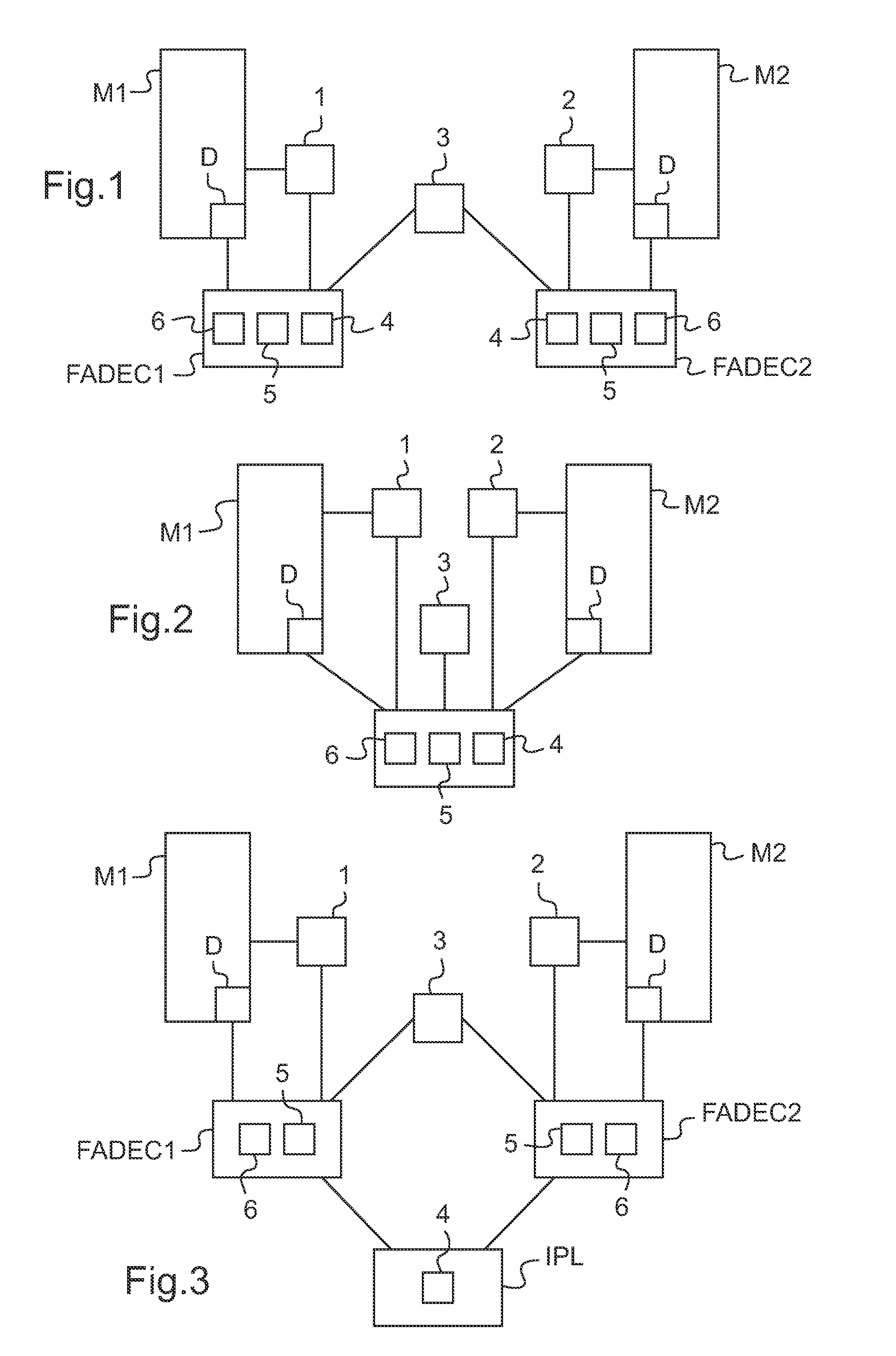
[0055]FIGS. 1 and 2 show variants of the invention.

[0056]With reference to FIG. 1, each engine M1, M2 includes a respective controlling electronic computer FADEC1, FADEC2 respectively controlling the fuel metering unit D of the engine M1, M2 to which it is connected, via regulation means 6.

[0057]Each controlling electronic computer is thus provided with regulation means 6, with control means 5 for accelerating or decelerating the engine, and in the first embodiment, with processor means 4.

[0058]Furthermore, the sensors 1, 2 transmit information respectively to the controlling electronic computers FADEC1, FADEC2 relating to first and second speeds of rotation NTL1 and NTL2 of the free turbines of the first and second engines M1, M2, which speeds are proportional to the substantially constant speed of rotation of the rotor of the rotorcraft that provides lift and propulsion.

[0059]Furthermore, a first setpoint, corresponding to the value that the first and second speeds of rotation NTL...


PUM


Abstract

The present invention relates to a method and to an associated fuel metering system for balancing the power delivered by two aircraft turboshaft engines by determining first and second limiting margins of the engines (M1, M2) which are transformed into first and second power margins. Thereafter, the values of the first and second power margins are compared in order to determine a primary difference between said first and second power margins. Finally, the engine having the greater power margin is accelerated in order to balance the first and second engines in power by minimizing the primary difference to as great as extent as possible.

Description

[0001]The present invention relates to a method and a system enabling the power from two turboshaft engines on an aircraft to be balanced. In particular, on a twin-engined rotorcraft, it is important to balance the power from the two engines so that both of them are subjected to similar amounts of damage, e.g. for the purpose of limiting maintenance actions, and so that the performance of the aircraft is optimized.BACKGROUND OF THE INVENTION[0002]Twin-engined rotorcrafts are generally provided with two free-turbine turboshaft engines. Power is then taken from a low pressure stage of each free turbine that rotates at about 20,000 revolutions per minute (rpm) to about 50,000 rpm. Thereafter, a gearbox is necessary to connect the free turbines to the main rotor that provides lift and propulsion since the speed of rotation of the rotor lies substantially in the range 200 rpm to 400 rpm: this is the main gearbox (MGB). It is also desirable to balance power from the engines so that each e...

Claims


Application Information

Patent Timeline
Patent Type & Authority Applications(United States)
IPC IPC(8): F23N5/18G05B13/02G06F19/00
CPCB64D31/12F02C9/28F02C9/42
Inventor GAULMIN, FRANCOIS-XAVIERIRAUDO, LIONELCHANIOT, DANIEL
Owner EUROCOPTER
Why Eureka
Try Eureka