Region-In-Object Measuring System, Computing Device for Measuring a Region-In-Object, Program for Measuring Region-In-Object and Computer Readable Recording Medium on Which the Program Is Recorded

a technology of region-in-object and computing device, which is applied in the direction of image enhancement, instruments, nuclear engineering, etc., can solve the problems of not being suited for the purpose of accurately knowing orientation, etc., to achieve accurate determination of the particular region inside the body, low cost, and accurate determination

Inactive Publication Date: 2008-11-06
GUNMA UNIVERSITY
View PDF2 Cites 5 Cited by
  • Summary
  • Abstract
  • Description
  • Claims
  • Application Information

AI Technical Summary

Benefits of technology

[0032]In accordance with the invention, with the use of a single two-dimensional X-ray photograph and the reference object, the orientation of the particular region inside a body can be accurately determined with respect to the image of the particular region inside the body at low costs as effort required for measurement and an X-ray radiation exposure to a patient are suppressed as much as possible.
[0033]In addition, in accordance with the invention, with the use of two or more of the two-dimensional X-ray photographs and the reference object, the three-dimensional location of the particular region inside a body can be determined accurately with respect to the image of the particular region inside the body at low costs as effort required for measurement and an X-ray radiation exposure to a patient are suppressed as much as possible.

Problems solved by technology

Although the shape and the location of the region of interest can be roughly known by the scheme, the scheme is not suited for the purpose of accurately knowing the orientation and the location of the particular region inside the body in order for injection in the mental foramen as described above.
Since X-rays are applied while the target object for inspection is being moved at a predetermined rate, it is not suited for the purpose of accurately knowing the orientation and the location of the particular region inside a body.
There is also a problem of the amount of exposure, and it is not suited for the purpose of accurately knowing the orientation and the location of the particular region inside a body as well.
However, it is not suited for the purpose of accurately knowing the orientation and the location of the particular region inside a body with respect to the reference position of the surface of the object for the purpose of injection in the mental foramen, for example.

Method used


Image

  • Region-In-Object Measuring System, Computing Device for Measuring a Region-In-Object, Program for Measuring Region-In-Object and Computer Readable Recording Medium on Which the Program Is Recorded
  • Region-In-Object Measuring System, Computing Device for Measuring a Region-In-Object, Program for Measuring Region-In-Object and Computer Readable Recording Medium on Which the Program Is Recorded
  • Region-In-Object Measuring System, Computing Device for Measuring a Region-In-Object, Program for Measuring Region-In-Object and Computer Readable Recording Medium on Which the Program Is Recorded

Examples


first embodiment

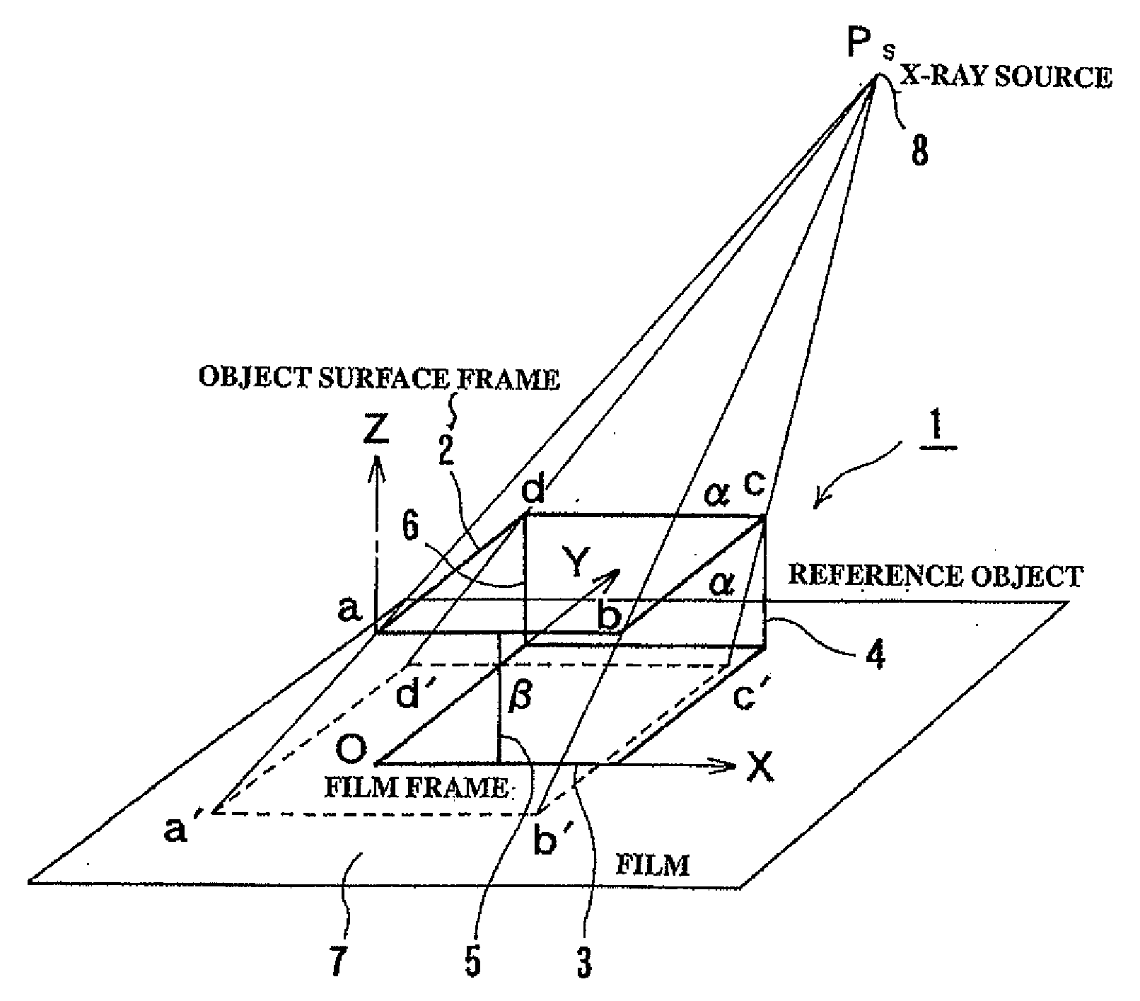
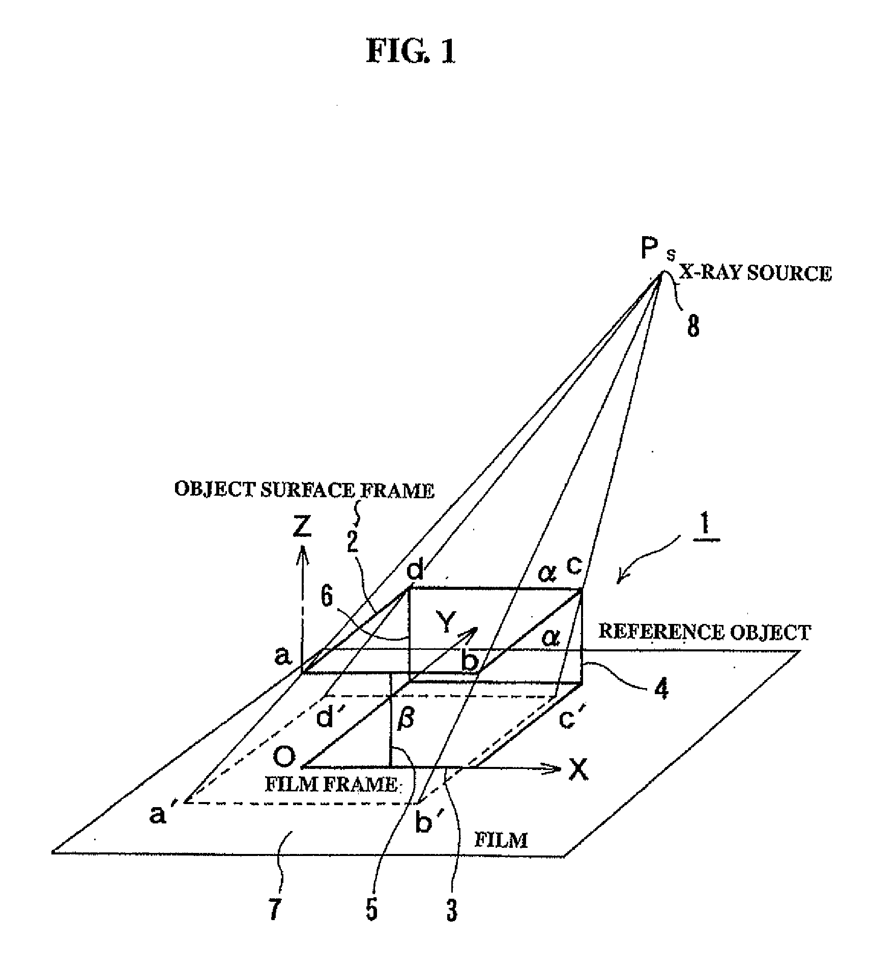
[0046]First, a region-in-object measuring system according to the present invention will be described. The region-in-object measuring system has a reference object and a computing device, in which a three-dimensional rectangular coordinate system is configured that has a predetermined point of the reference object as an origin point, and the orientation of a particular region inside an object is determined with respect to a reference position of the surface of the object (the location of the image of the particular region in an X-ray image).

[0047]As shown in FIG. 1, a reference object (1) has two frames (2) and (3) separated from each other. One frame (2) is a frame that is closely contacted with the surface of the object, and the other frame (3) is a frame that is closely contacted with an X-ray film. In the specification of the application, the frame (2) that is closely contacted with the surface of the object is referred to as “an object surface frame”, and the frame (3) that is ...

second embodiment

[0100]As described above, the second embodiment has been described in which a particular region inside an object is determined by two X-ray photographs. In accordance with the present invention, a particular region inside an object can be determined by three or more of X-ray photographs, and in that case, the accuracy is more improved.

[0101]For example, the case is considered in which three X-ray photographs are obtained. Pairs formed of these photographs are three pairs, (photo 1, photo 2), (photo 2, photo 3), and (photo 3, photo 1). Suppose the target locations computed from the three pairs are [R(12)], [R(23)], and [R(31)]. As expressed by the following equation, when they are averaged to be a target location [R], more accurate measurement can be implemented.

[R]=13([R(12)]+[R(23)]+[R(31)])(22)

[0102]Next, third and fourth embodiments according to the application will be described.

[0103]In the first embodiment and the second embodiment, the X-ray film is placed as closely contacted...


PUM


Abstract

A region-in object measuring system comprises a reference object (1) having two frames, i.e., an object surface frame (2) brought into contact with the surface of an object and a film frame (3) with which an X-ray film (7) is brought into contact, spaced from each other and a computing device. The computing device sets a three-dimensional X-ray coordinate system using the reference object (1) according to a two-dimensional X-ray image acquired by imaging a region in an object in a state that the object surface frame (2) of the reference object (1) is in close contact with the surface of the object by means of an X-ray imaging apparatus, determining the position of an X-ray source from the projection magnification and size of the image of the object surface frame (2), determining the position vector of a specific region in a body according to the position of the X-ray source, and accurately determines the direction and three-dimensional position of the region in the object with respect to the position of the image of the region in the object shown on the X-ray image.

Description

TECHNICAL FIELD[0001]The present invention relates to a region-in-object measuring system, a computing device for measuring a region-in-object, a program for measuring a region-in-object and a computer readable recording medium on which the program is recorded. More specifically, the present invention relates to a novel region-in-object measuring system, a computing device for measuring a region-in-object, a program for measuring a region-in-object and a computer readable recording medium on which the program is recorded, using a two-dimensional X-ray photograph to accurately determine the orientation or the location of a particular region inside an object.BACKGROUND ART[0002]Generally, it is sometimes desired to determine the location and the orientation of a particular region inside an object from outside the object. For a specific medical example, there is an injection in a mental foramen in the operation of oral surgery. The mental foramen is a hole of a few millimeters in a sku...

Claims


Application Information

Patent Timeline
Patent Type & Authority Applications(United States)
IPC IPC(8): H05G1/30G03B42/02
CPCG06T2207/10116G06T2207/30036A61B6/022A61B6/12A61B19/52A61B2019/5289G06T7/0042A61B90/36A61B2090/364G06T7/73
Inventor OHTA, NAOYAMOGI, KENJINAKASONE, YOSHIKI
Owner GUNMA UNIVERSITY
Why Eureka
Try Eureka