Multilayered microcavities and actuators incorporating same

a technology of actuators and microcavities, applied in the field of cavities, can solve the problems of inefficiency and high cost of manufacturing techniques, and achieve the effect of introducing new designs of certain embodiments

Active Publication Date: 2008-11-13
DESAI AMISH +4
View PDF6 Cites 24 Cited by
  • Summary
  • Abstract
  • Description
  • Claims
  • Application Information

AI Technical Summary

Benefits of technology

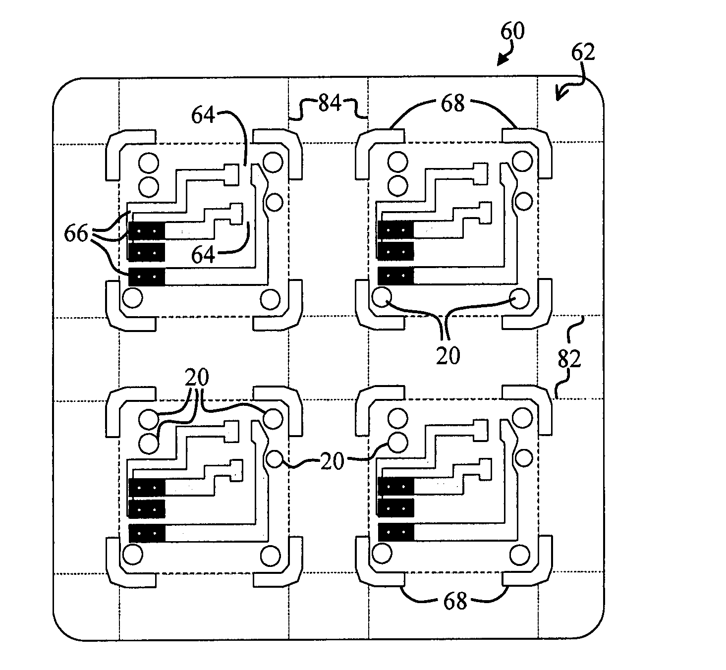
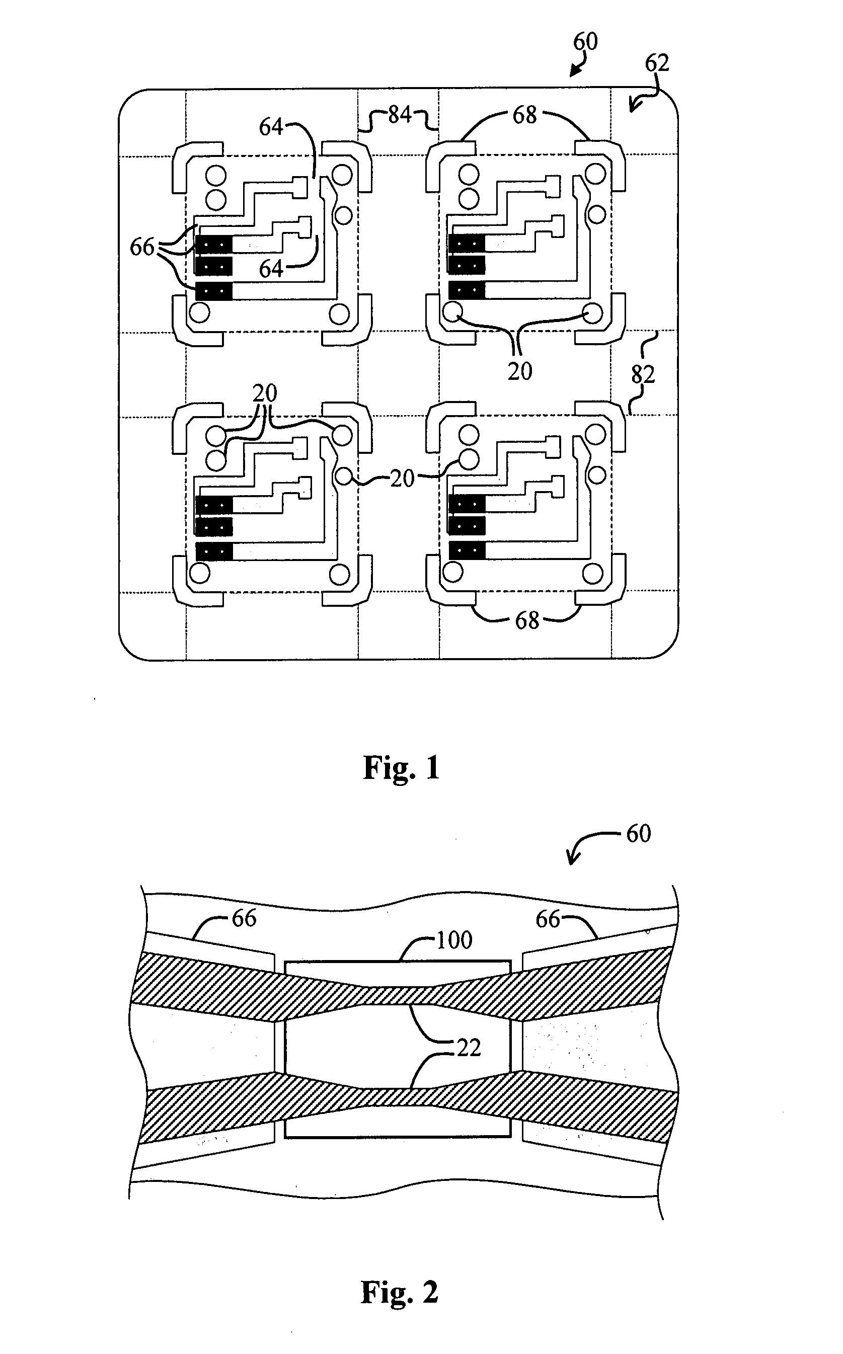
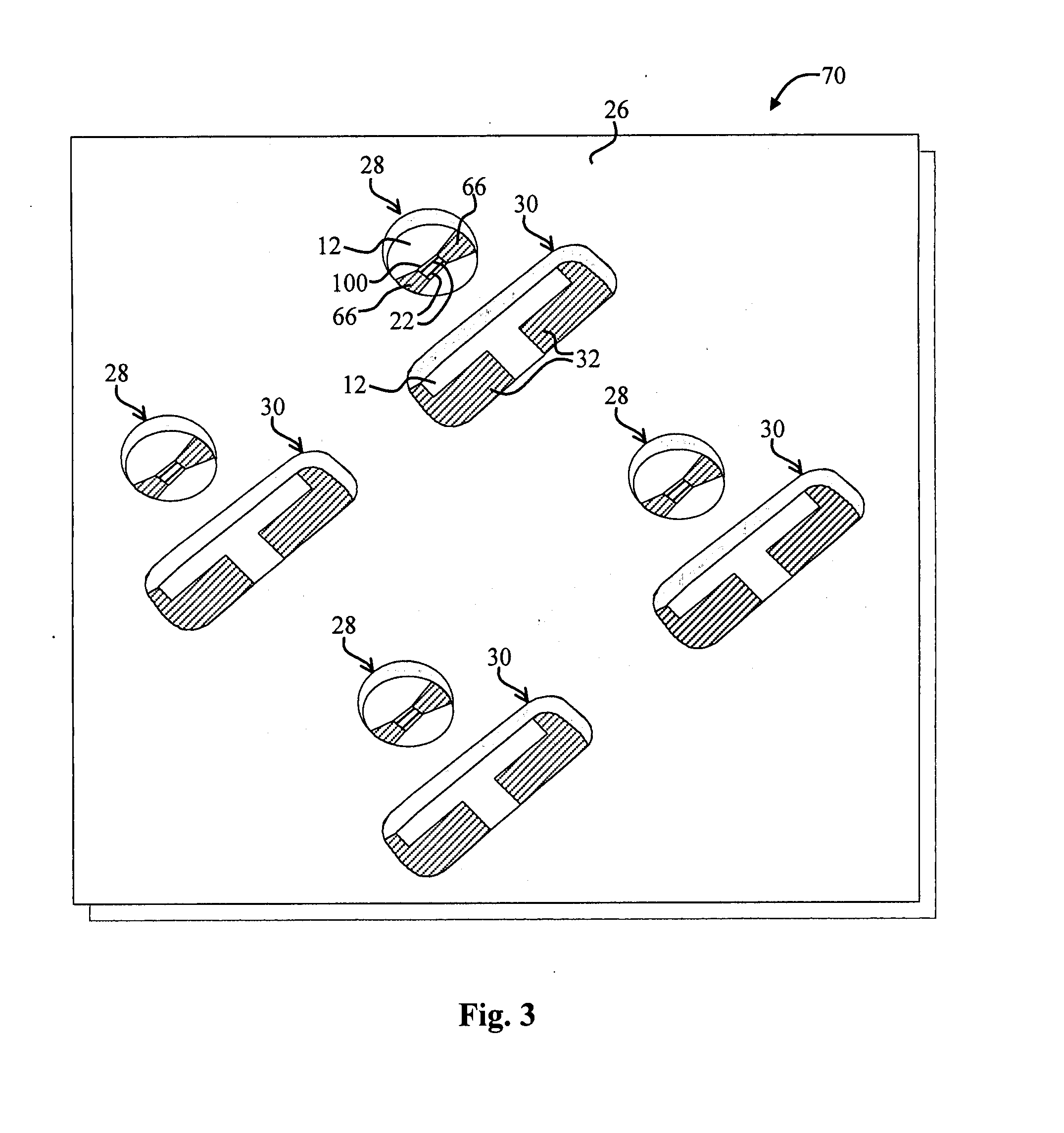
[0014]The novel design of certain embodiments of the present invention is facilitated by the use of different substrate layers to create desired circuit features, such as microcavities. Conventionally, expensive and time-consuming processes were employed to etch microcavities in silicon wafers; load the microcavities with explosives and an accompanying bridgewires; dice the wafers into various segments, with each segment having a cavity; robotically place the corresponding segments onto a circuit board; bond the segments to the circuit board, and so on. Certain embodiments of the present invention may be cost-effectively manufactured without such expensive and tedious production steps.

Problems solved by technology

Unfortunately, such manufacturing techniques are often undesirably expensive and inefficient.

Method used


Image

  • Multilayered microcavities and actuators incorporating same
  • Multilayered microcavities and actuators incorporating same
  • Multilayered microcavities and actuators incorporating same

Examples


Embodiment Construction

[0025]While the present invention is described herein with reference to illustrative embodiments for particular applications, it should be understood that the invention is not limited thereto. Those having ordinary skill in the art and access to the teachings provided herein will recognize additional modifications, applications, and embodiments within the scope thereof and additional fields in which the present invention would be of significant utility.

[0026]For the purposes of the present discussion, an initiator may be any device or module that initiates or starts an action in response to an input signal or sensed condition. A sensor may be any device or module that senses or detects a condition or environmental variable and provides a signal, such a mechanical or electrical signal, in response thereto. Accordingly, an initiator may be a type of sensor, and an initiator may incorporate a sensor, such as to facilitate selectively initiating an action. An igniter may be any actuator...


PUM


Abstract

A microcavity structure. In an illustrative embodiment, the microcavity structure includes a first substrate, which has a region of interest. A second substrate with a perforation therein is bonded to the first substrate. The perforation coincides with the region of interest. In a specific embodiment, the first substrate is implemented via a Printed Circuit Board (PCB). The region of interest includes one or more circuit components, including an actuator, such as a bridgewire, thereon or therein. A smoothing layer is included between the PCB and the actuator. A bonding gasket adheres the first substrate to the second substrate. The perforation accommodates energetic material that is selectively ignited via the actuator.

Description

ACKNOWLEDGEMENT OF GOVERNMENT SUPPORT[0001]This invention was made with Government support under Contract No. W15QKN-04-C-1130 awarded by the United States Army. The Government has certain rights to this invention.BACKGROUND OF THE INVENTION[0002]1. Field of Invention[0003]This invention relates to cavities and accompanying substrates in which the cavities are formed. Specifically, the present invention relates to cavities that are coupled to circuits or other features and further relates to methods for creating such cavities.[0004]2. Description of the Related Art[0005]Cavities are employed in various demanding applications including micro thrusters, airbag initiators, and initiators for munitions. Such applications often demand cost-effective explosive-filled microcavities that can be readily positioned and coupled to a control circuit.[0006]Initiators often include a heating element, such as a bridgewire or reactive bridge, which is adjacent to an energetic material. For the purp...

Claims


Application Information

Patent Timeline
Patent Type & Authority Applications(United States)
IPC IPC(8): F42B3/13H05K1/00
CPCF42B3/13H05K1/0212H05K1/16H05K3/281H05K3/4611H05K2201/09063H05K2203/063
Inventor DESAI, AMISHMELENDES, BOBLU, MINGFUCHS, BRIANCHAU, STEPHEN
Owner DESAI AMISH
Why Eureka
Try Eureka