Mobility assistance device

Active Publication Date: 2008-11-13
ROWANWOOD IP
View PDF41 Cites 9 Cited by
  • Summary
  • Abstract
  • Description
  • Claims
  • Application Information

AI Technical Summary

Benefits of technology

[0036]In another embodiment, the walker frame further comprises a canopy, which may be a sun canopy to provide shade from the sun or a rain canopy (e.g., like an umbrella) to provide protection from rain, positioned above the open area of the upper portion. If the walker frame is provided with an optional seat, then the canopy may be positioned to provide cover for a person seated on such an optional seat. Alternately, or in addition, the walker frame may be provided with a child or baby seat, in which case a canopy may be positioned to provide cover for a child or baby seated on such an optional seat. Alternately, or in addition, t

Problems solved by technology

This configuration moves the turning fulcrum of the walker toward the front,

Method used


Image

  • Mobility assistance device
  • Mobility assistance device
  • Mobility assistance device

Examples


Embodiment Construction

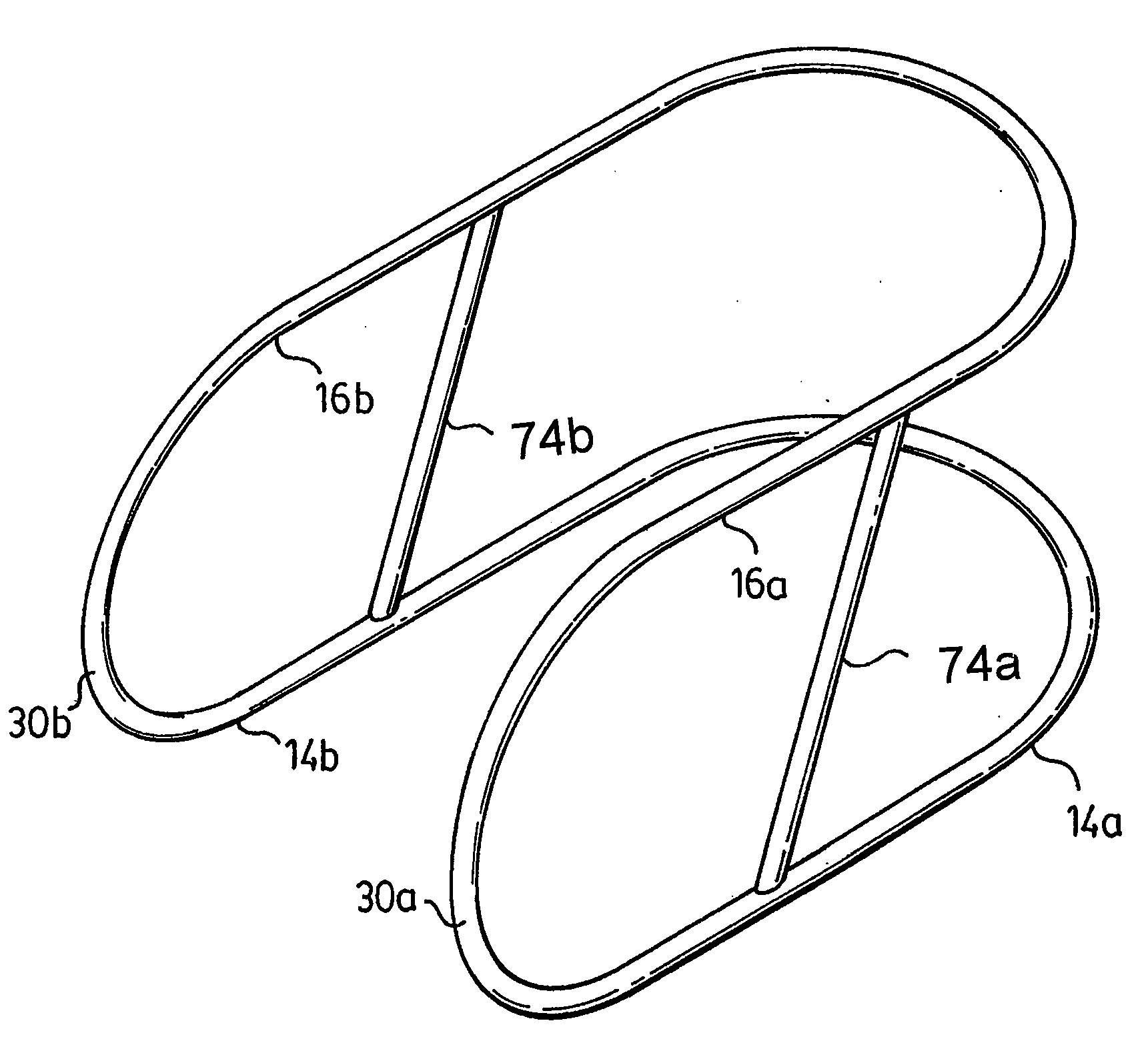
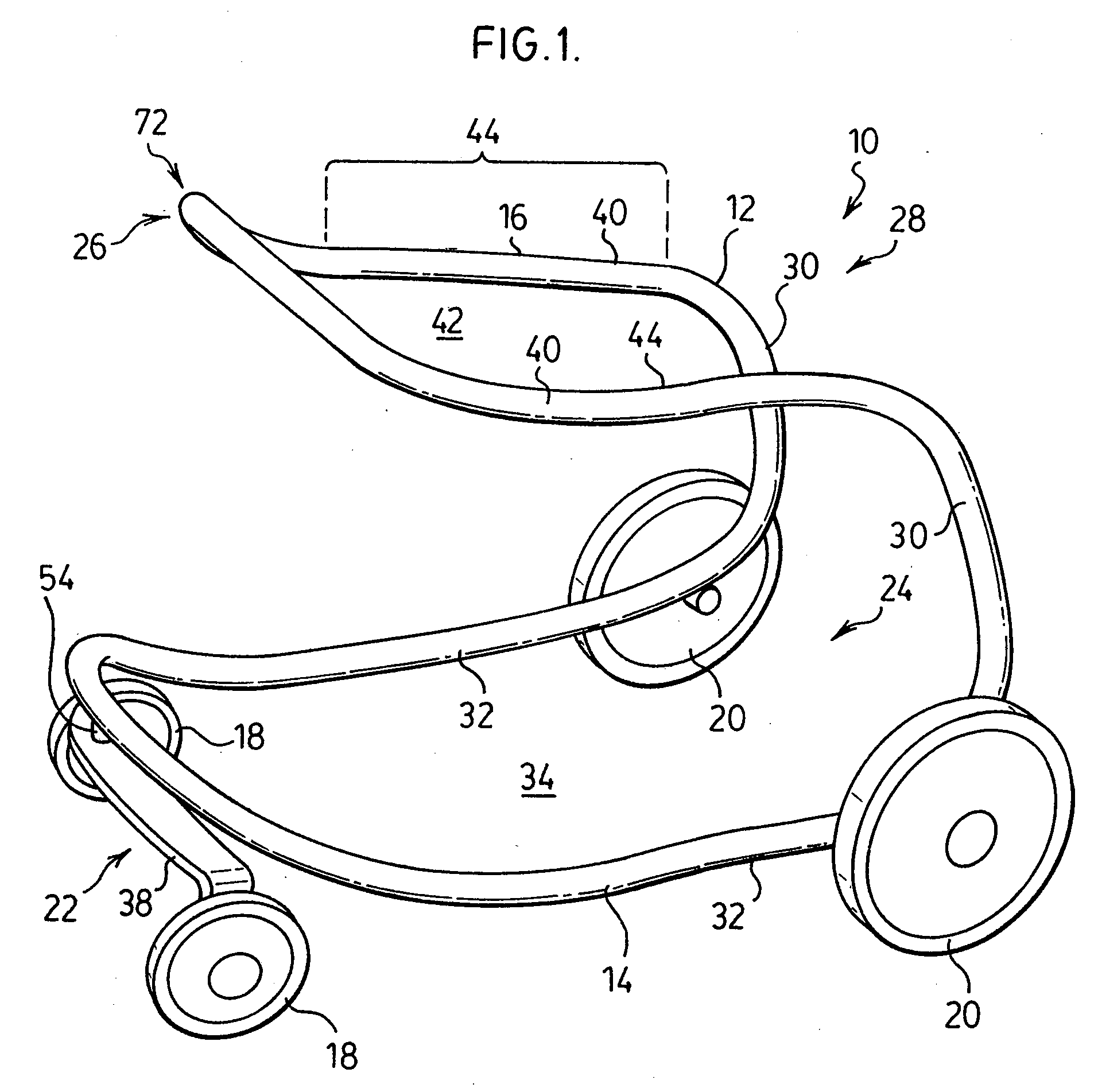
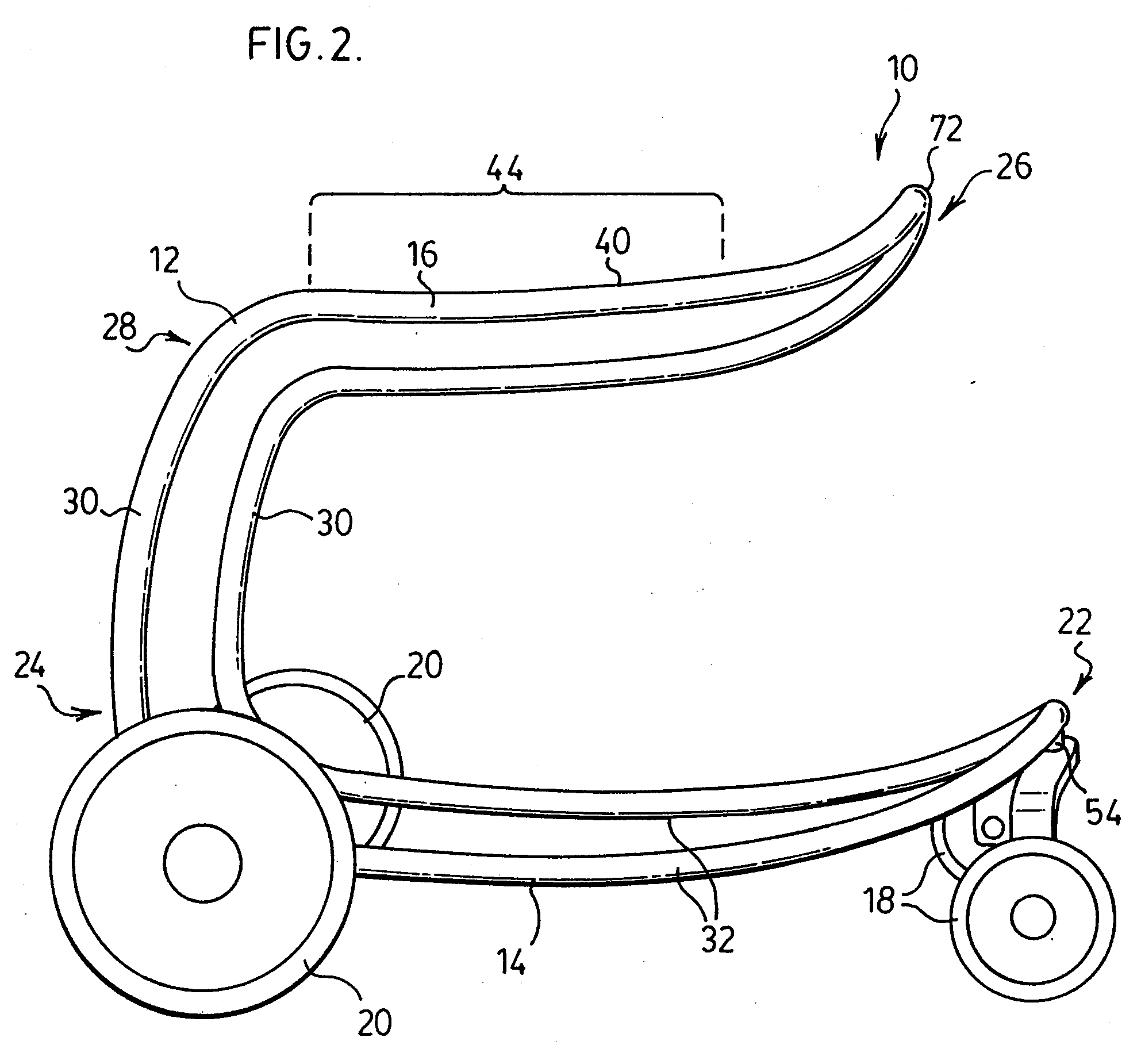
[0105]Referring to FIGS. 1-4, walker 10 comprises walker frame 12, which comprises base or lower portion 14 and upper portion 16. In this preferred embodiment, base portion has directly mounted thereto a pair of front wheels 18 and a pair of rear wheels 20. Base portion has a front end 22 and a rear end 24. Similarly, upper portion 16 has a front end 26 and a rear end 28. Upper portion 16 is secured above base portion 14 by first and second support members 30.

[0106]Base portion 14 is generally U-shaped and has first and second generally longitudinally extending, spaced apart, opposed side members 32 which define a generally open area 34 therebetween. Base portion 14 is adapted to have surface engaging members, such as wheels 18, 20, affixed directly thereto. For example, as shown in FIGS. 1, rear wheels 20 are affixed directly to rear end 24 of base portion 14 or to a spur or extension 76 of the base portion 14 as exemplified in FIGS. 12 and 13, by, e.g. horizontally extending helic...


PUM


Abstract

A walker frame is provided which has a generally open space frame and has handle portions that are cantilevered.

Description

FIELD OF THE INVENTION[0001]This invention relates to a device to assist people, especially the elderly or disabled, to travel under their own power. In a particularly preferred embodiment, the present invention relates to a walker.BACKGROUND OF THE INVENTION[0002]Mature adults, including the elderly, typically suffer a decrease in mobility as they age. This may include loss of stability as well as a loss of strength in the lower limbs requiring the use of canes, crutches or the like to permit a person to continue to travel under their own power without the assistance of another person. In addition, some disabled individuals or individuals undergoing rehabilitation therapy may require assistance walking.[0003]Various different types of walkers and stabilization devices have been developed to assist the elderly, as well as individuals recovering from an accident or surgery. For example, Crnkovich (U.S. Pat. No. 7,001,313) discloses an exercise assistance device that uses an upper han...

Claims


Application Information

Patent Timeline
IPC IPC(8): A61H3/00
CPCA61H3/04A61H2003/046A61H2201/1633
Inventor JOWETT, E. CRAIGJOWETT, CHRISTOPHER D.
Owner ROWANWOOD IP
Why Eureka
Try Eureka