
System and methods for inspecting internal cracks

a technology of internal cracks and inspection methods, applied in the direction of material magnetic variables, digital computer details, instruments, etc., can solve the problems of affecting introducing defects, or other anomalies in the material, and limiting the useful life of components

Inactive Publication Date: 2008-11-13
GENERAL ELECTRIC CO
View PDF21 Cites 13 Cited by
  • Summary
  • Abstract
  • Description
  • Claims
  • Application Information

AI Technical Summary

Problems solved by technology

The rotating components are subject to substantial centrifugal loads during operation, which generate corresponding stress that must be limited for maximizing component life.
In addition, defects, flaws, or other anomalies in the material may be introduced during the original manufacture of the engine components, or may occur during the operational life thereof.
Accordingly, the engine components are typically inspected during the manufacturing process, and during routine maintenance outages, for uncovering any anomaly therein, which might limit the useful life of the components.
A defect or geometric abnormality in the material, which changes the homogeneity thereof, will disturb the eddy current.
Crack detection is particularly important in turbine engine components since cracks may propagate under stress and substantially reduce the useful life of a component, and may eventually lead to component failure if not suitably accommodated.
Small or minute cracks in an internal channel are difficult to detect visually, and can substantially reduce the useful life of the specimen.
In addition, the geometry effects of such internal cavities give rise to substantial noise in the response signal such that small cracks and other fine defects cannot be detected using conventional EC inspection techniques.

Method used


Image

  • System and methods for inspecting internal cracks
  • System and methods for inspecting internal cracks
  • System and methods for inspecting internal cracks

Examples


Embodiment Construction

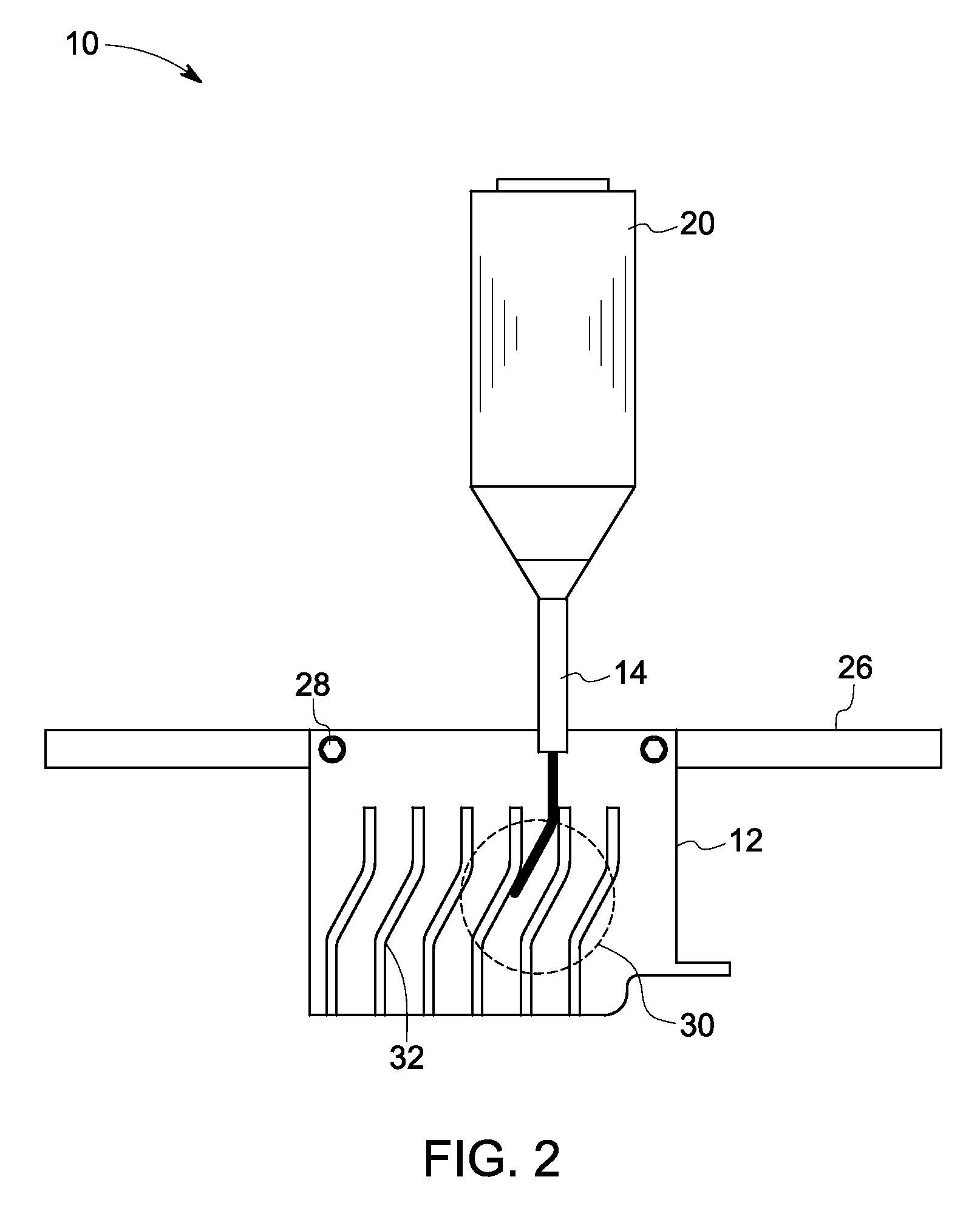
[0017]As discussed in detail below, embodiments of the invention include a system and methods for inspecting internal cracks. As used herein, the term ‘internal cracks’ refers to anomalies at a region of interest located inside a cavity on an internal surface, either on a convex airfoil side or on a concave airfoil side of a blade. The internal surface on the convex side of a part is more difficult to access from outside than the one on a concave side. Some non-limiting examples of the anomalies include cracks and pits.

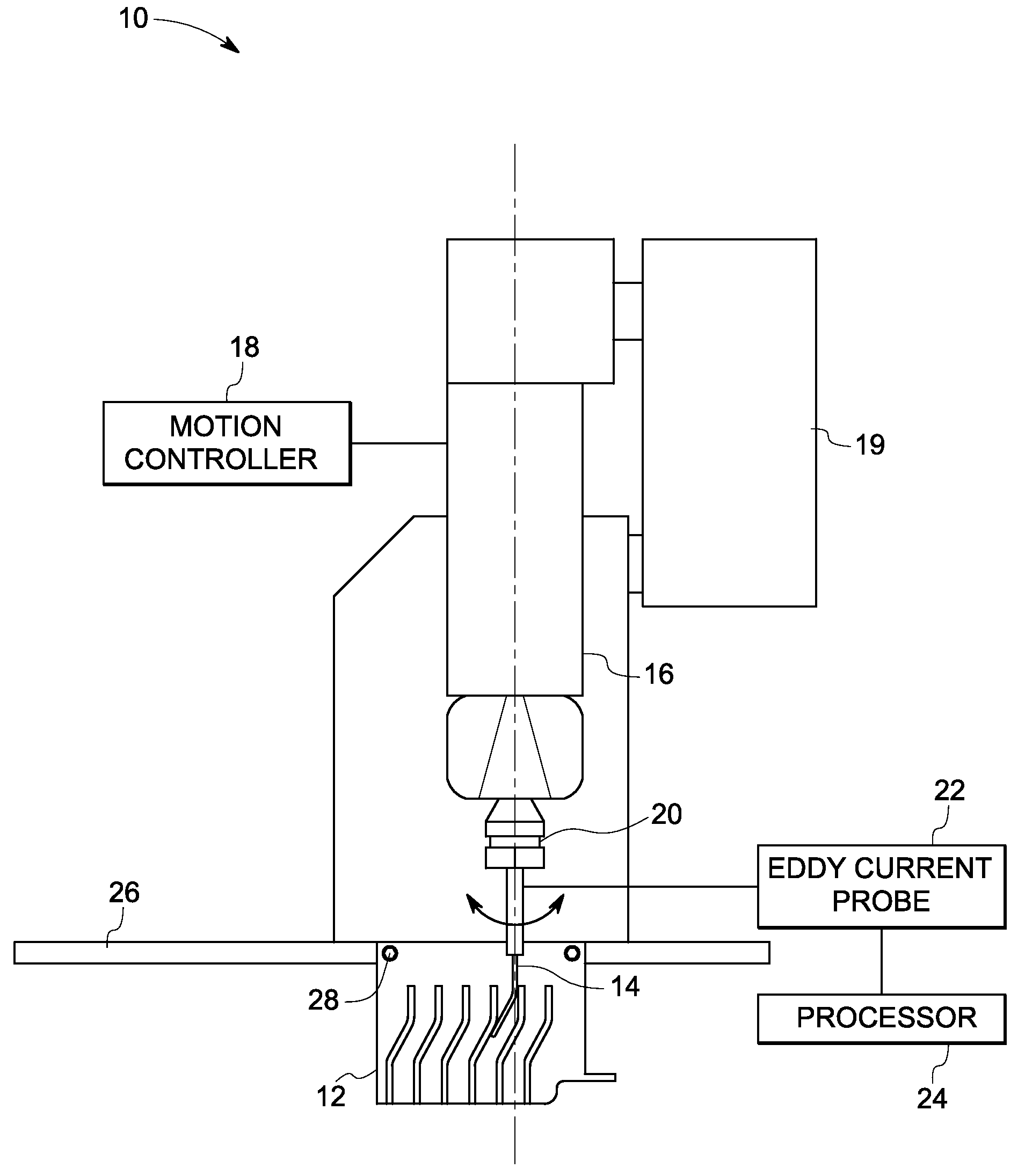
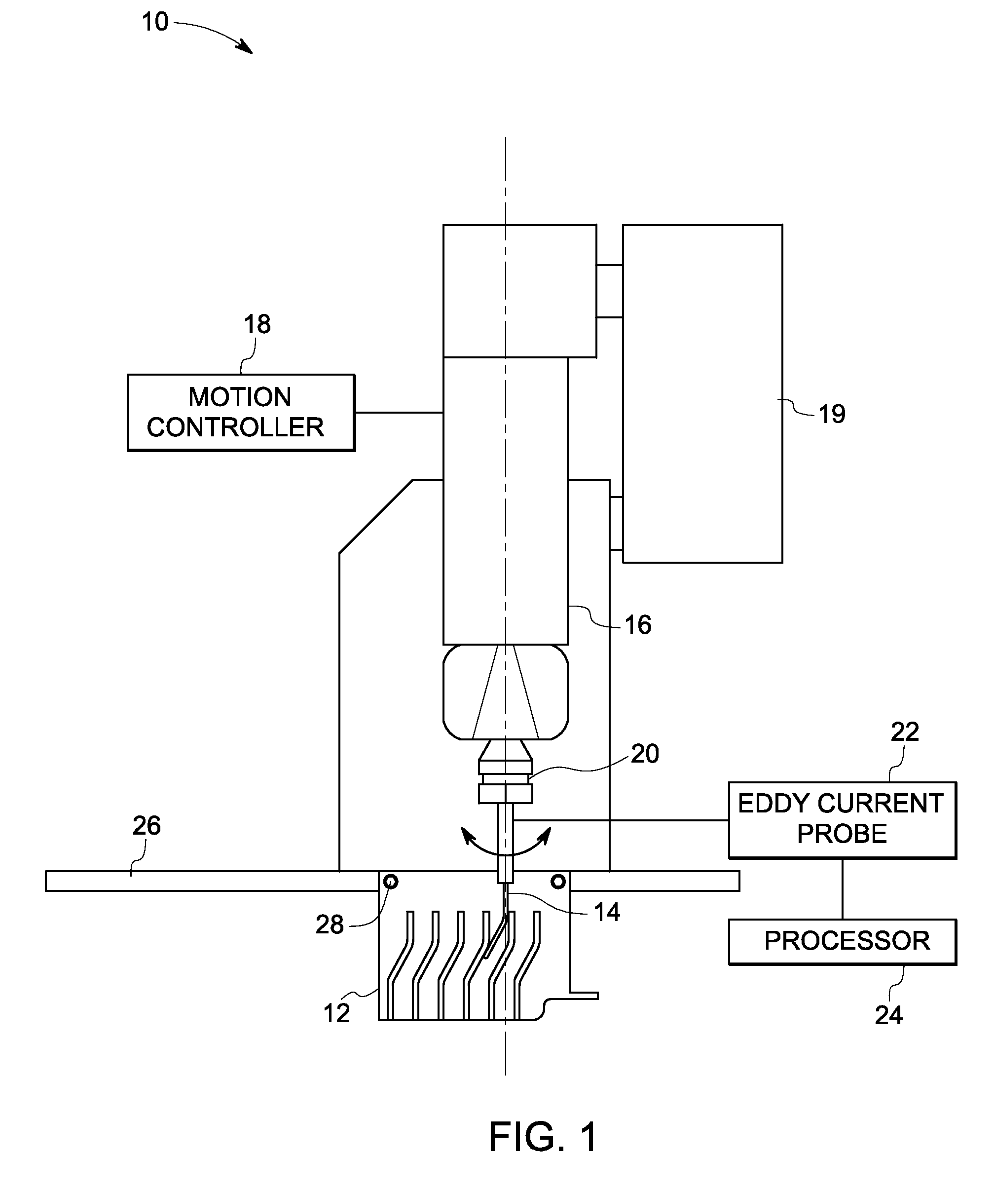
[0018]Turning to the drawings, FIG. 1 is a diagrammatic illustration of an inspection system 10 used to detect internal cracks in a part 12. In a particular embodiment, the part 12 is a blade used in an aircraft engine. The inspection system 10 includes an eddy current probe 14 configured to induce eddy currents in the part 12. The eddy current probe 14 may be moved relative to the part 12 by a robot 16. As used herein, the term ‘robot’ refers to a single or a multi-a...


PUM

PropertyMeasurementUnit
multifrequency phase analysisaaaaaaaaaa
movementaaaaaaaaaa
currentaaaaaaaaaa

Abstract

A method for inspecting an internal cavity in a part is provided. The method includes inserting a probe into the internal cavity. The method also includes controlling movement of the probe using a defined scan path to scan the probe over a region of interest in the internal cavity. The method also includes applying multiple multifrequency excitation signals to the probe to generate a number of multifrequency response signals. The multifrequency excitation signals are applied at multiple positions within the internal cavity. The method further includes performing a multifrequency phase analysis on the multifrequency response signals to inspect the internal cavity.

Description

BACKGROUND[0001]The invention relates generally to nondestructive testing and more specifically, to eddy current inspection of manufactured components.[0002]Gas turbine engines include rotating shafts and disks, which support rotating blades in the fan, compressor, high pressure turbine, and low pressure turbine. The rotating components are subject to substantial centrifugal loads during operation, which generate corresponding stress that must be limited for maximizing component life. In addition, defects, flaws, or other anomalies in the material may be introduced during the original manufacture of the engine components, or may occur during the operational life thereof. Accordingly, the engine components are typically inspected during the manufacturing process, and during routine maintenance outages, for uncovering any anomaly therein, which might limit the useful life of the components.[0003]A common, non-destructive inspection technique is eddy current (EC) inspection of typicall...

Claims


Application Information

Patent Timeline
Patent Type & Authority Applications(United States)
IPC IPC(8): G01N27/90G01R33/14G01M99/00
CPCG01N27/902G01N27/9046
Inventor WANG, CHANGTINGNATH, SHRIDHAR CHAMPAKNATHGRIFFIN, WESTON BLAINEFIELDS, MICHAEL WAYNEHALLMAN, DARREN LEEAL-KHALIDY, ABDUL RAHMAN ABDALLAH
Owner GENERAL ELECTRIC CO
Learn More