
Inspection method and system using multifrequency phase analysis

a phase analysis and multi-frequency technology, applied in the field of inspection techniques, can solve the problems of increasing manufacturing costs, unable to detect flaws in the region of approximately 1.5 mm or less near the surface of the material of the part, and exhibiting poor signal to noise ratio (snr), so as to improve the near surface detection effect, enhance the signal to noise ratio, and good signal to noise ratio

Active Publication Date: 2006-09-28
GENERAL ELECTRIC CO
View PDF3 Cites 12 Cited by
  • Summary
  • Abstract
  • Description
  • Claims
  • Application Information

AI Technical Summary

Benefits of technology

[0007] Multi-frequency eddy current techniques concentrate electromagnetic energies at a few frequencies and yield good signal to noise ratios using lock-in amplifiers. A subsurface eddy current multifrequency inspection technique that enhances the signal to noise ratio and improves the near surface detection in deeper locations within the part to be inspected, is therefore desired.

Problems solved by technology

However, even with the use of special probes and pulser instrumentation, UT techniques generally cannot detect flaws in the region of approximately 1.5 mm or less near the surface of the material of the part to be inspected.
However, the addition of this material generally increases the manufacturing cost due to material waste and production time.
However, these techniques typically exhibit a poor signal to noise ratio (SNR) for small flaws under the surface due to an “electromagnetic skin effect,” which limits the penetration of eddy currents into the material under test.
However, the pulsed eddy current technique typically requires complicated signal processing developments, as well as high-speed data acquisition and processing systems.

Method used


Image

  • Inspection method and system using multifrequency phase analysis
  • Inspection method and system using multifrequency phase analysis
  • Inspection method and system using multifrequency phase analysis

Examples


examples

[0035] As described herein, multifrequency phase analysis was applied to detect subsurface defects on an exemplary inspection part. FIG. 5 is an illustration of an exemplary inspection part containing a number of holes representing subsurface defects. The inspection part 30 is fabricated on Titanium 6-4 material and comprises a top plate 32 of thickness T and a 0.2″ base plate 34. Three duplicated rows of flat bottom holes 36 of diameter 1 / 64″, 1.5 / 64″, 2 / 64″, 3 / 64″, 4 / 64″ are introduced on the bottom of the top plate 32, with a spacing of half an inch between them. The flat bottom holes are 0.040″ in height. The thickness T of the top plates, range from 0.050″ to 0.10″ and the flat bottom holes 36 are located at 0.010″ to 0.060″ beneath the top surface of the top plate 32.

[0036]FIG. 6 depicts images generated as a result of the application of a single frequency eddy current on the exemplary inspection part illustrated in FIG. 5. A single frequency eddy current inspection was initi...


PUM


Abstract

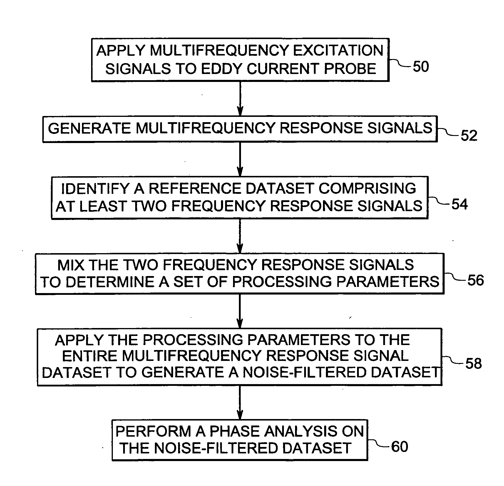
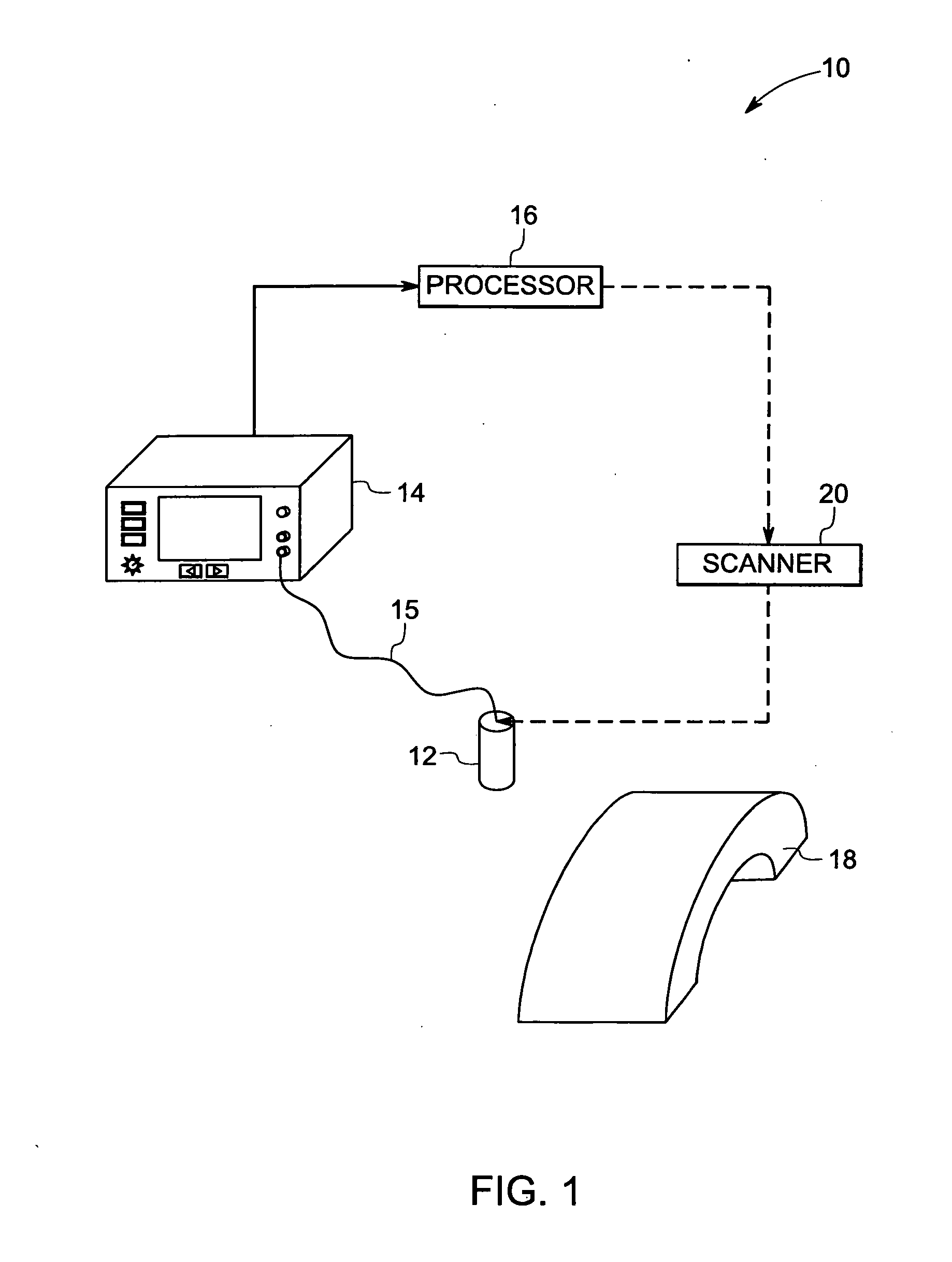
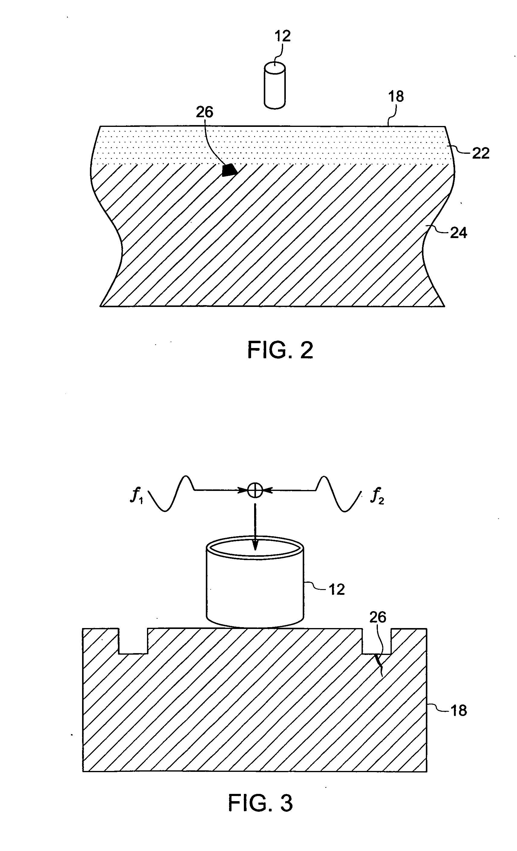
A method for inspecting a part is provided. The method includes applying a number of multifrequency excitation signals to a probe to generate a number of multifrequency response signals for the part being inspected. The method further includes performing a multifrequency phase analysis on the multifrequency response signals to inspect a subsurface of the part. An inspection system is provided and includes an eddy current (EC) probe configured to induce eddy currents in a part. The system further includes an eddy current instrument coupled to the EC probe and configured to apply multifrequency excitation signals to the EC probe to generate multifrequency response signals. The system further includes a processor configured to analyze the multifrequency response signals from the EC instrument by performing a multifrequency phase analysis, to inspect a subsurface of the part.

Description

CROSS REFERENCE TO RELATED APPLICATIONS [0001] This application is a non-provisional application of provisional application Ser. No. 60 / 660032, entitled “Blind Zone Inspection with Eddy Current using Multifrequency and Phase Analysis”, filed Mar. 9, 2005, which is herein incorporated by reference.BACKGROUND [0002] The invention relates generally to inspection techniques and more particularly to a method and system for performing subsurface defect inspections using a multifrequency phase analysis eddy current technique. [0003] A number of different non-destructive inspection techniques have been proposed such as ultrasonic testing (UT), eddy current inspection techniques and surface acoustic techniques. Exemplary eddy current inspection techniques include pulsed eddy current techniques and multi-frequency eddy current techniques. Eddy current techniques are performed to detect anomalies in material surfaces as well as to detect anomalies deep within material surfaces. Eddy current in...

Claims


Application Information

Patent Timeline
Patent Type & Authority Applications(United States)
IPC IPC(8): G01R19/00
CPCG01N27/9046G01N27/9086
Inventor WANG, CHANGTINGMCKNIGHT, WILLIAM STEWARTSUH, UIERTEKIN, SERKAN
Owner GENERAL ELECTRIC CO
Learn More