Method of and system for controlling thermal head and stencil material roll

a control system and thermal head technology, applied in the field of thermal head control system, can solve the problems of deteriorating image quality, affecting the accuracy of stencil material setting, etc., and achieve the effect of accurate calculation

Inactive Publication Date: 2008-11-13
OSHIMA KENJI +2
View PDF5 Cites 0 Cited by
  • Summary
  • Abstract
  • Description
  • Claims
  • Application Information

AI Technical Summary

Benefits of technology

[0036]In the first thermal head control method and system of the present invention, the heating energy to the thermal head is controlled on the basis of the residue of the stencil material in the stencil material roll, that is, the heating energy to the thermal head is increased by the degree of deterioration of the surface smoothness of the stencil material due to reduction of the residue. Accordingly, the heating energy to the thermal head can be controlled according to the surface condition of the stencil material without adding to the overall size of the system or the cost of the system. Accordingly, deterioration of the quality of the printed image due to fluctuation in perforations can be avoided.
[0039]In the second thermal head control method and system of the present invention, the heating energy to the thermal head is controlled on the basis of the elapsed time from the production of the stencil material roll. Accordingly, when the surface smoothness of the stencil material deteriorates due to that the time has elapsed from the production of the stencil material roll, the heating energy to the thermal head can be controlled according to the surface condition of the stencil material without adding to the overall size of the system or the cost of the system. Accordingly, deterioration of the quality of the printed image due to fluctuation in perforations can be avoided.
[0042]In the first stencil material roll of the present invention which is provided with a storage means which stores residue data according to the residue of the stencil material, for instance, even when a partly used stencil material roll is installed, a residue of the stencil material in the partly used stencil material roll can be automatically obtained and a residue of the stencil material can be accurately calculated thereafter. Further, even if a stencil material roll whose total length is not known to the operator is installed, the total length of the stencil material roll can be automatically obtained.

Problems solved by technology

However, the surface smoothness of the stencil material roll to be brought into close contact with the thermal head deteriorates as compared with the surface smoothness of the stencil material in the form of a sheet before it is rolled for, for instance, the rolling pressure when the stencil material is rolled into a roll.
When the surface smoothness of the stencil material deteriorates, the thermal head is variously brought into contact with the stencil material and sites easy to perforate and sites difficult to perforate are generated in the stencil material, whereby the quality of the printed images deteriorates.
However, the method disclosed in Japanese Unexamined Patent Publication No. 2002-79646 is disadvantageous in that visual detection of the surface condition of the stencil material is limited and setting of the suitable heating energy to the thermal head is sometimes impossible, and optical detection of the surface condition of the stencil material adds to the overall size of the system and to the cost of the system.

Method used


Image

  • Method of and system for controlling thermal head and stencil material roll
  • Method of and system for controlling thermal head and stencil material roll
  • Method of and system for controlling thermal head and stencil material roll

Examples


Embodiment Construction

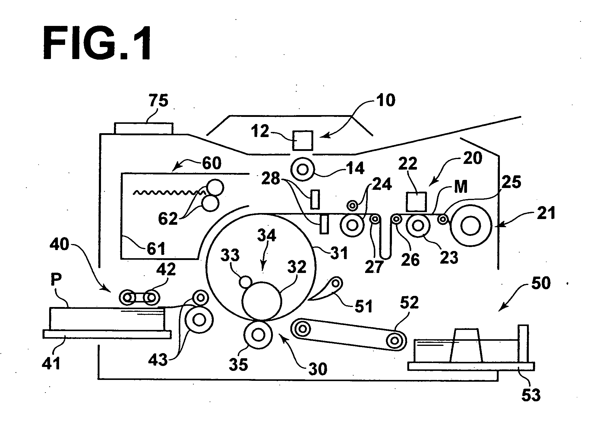
[0049]A stencil printer employing a thermal head control system in accordance with an embodiment of the present invention will be described with reference to the drawings, hereinbelow. FIG. 1 is a view showing in brief the stencil printer.

[0050]As shown in FIG. 1, the stencil printer comprises a reading portion 10 which reads out an image on an original, a stencil making portion 20 which makes a stencil from stencil material on the basis of the image information read by the reading portion 10, a printing portion 30 which prints on a printing paper by the use of the stencil M made by the stencil making portion 20, a paper supply portion 40 which supplies the printing paper to the printing portion 30, a paper discharge portion 50 which discharges the printed printing paper from the printing portion 30, and a stencil discharge portion 60 which discharges the stencil M after use.

[0051]The image read-out portion 10 is an image scanner and comprises an image line sensor 12 which reads out...


PUM


Abstract

In a thermal head control system for controlling heating energy to a thermal head perforating stencil material unrolled from a stencil material roll, the heating energy to a thermal head is controlled according to the surface condition of the stencil material. The residue of stencil material M in a stencil material roll (21b) is calculated by a residue calculating means (65) and the elapsed time of the stencil material roll from production thereof is obtained on the basis of date data on the date of production of the stencil material roll stored in a storage portion (70) of the stencil material roll (21b). Further, kind data on the kind of the stencil material stored in the storage portion (70) is obtained and the heating energy is obtained on the basis of the residue, the elapsed time and the kind data. On the basis of this heating energy, the heating action of the thermal head (22) is controlled.

Description

FIELD OF THE INVENTION[0001]This invention relates to a thermal head control system which controls heating energy to a thermal head which perforates stencil material unrolled from a stencil material roll.BACKGROUND OF THE INVENTION[0002]There have been variously proposed stencil printers where print is made by driving, for instance, a thermal head according to image data obtained by reading out an original by, for instance, a scanner to selectively melt and perforate stencil material to make a stencil, winding the stencil around a printing drum, supplying ink inside the printing drum, and transferring the ink to printing papers through the stencil by, for instance, a roller.[0003]In the stencil printers described above, a stencil material roll into which the stencil material is rolled is employed to improve the operability. However, the surface smoothness of the stencil material roll to be brought into close contact with the thermal head deteriorates as compared with the surface smo...

Claims


Application Information

Patent Timeline
Patent Type & Authority Applications(United States)
IPC IPC(8): B41J2/00B41L13/00B41J2/325B41C1/055B41C1/14B41L13/06B41L13/14B41N1/24
CPCB41C1/144B41L13/06B41N1/248
Inventor OSHIMA, KENJIISOZAKI, TAKASHIOHASHI, MORIO
Owner OSHIMA KENJI
Why Eureka
Try Eureka