Electronic control apparatus

Active Publication Date: 2008-11-13
MITSUBISHI ELECTRIC CORP
View PDF17 Cites 63 Cited by
  • Summary
  • Abstract
  • Description
  • Claims
  • Application Information

AI Technical Summary

Benefits of technology

[0007]Accordingly, the present invention is intended to obviate the problem as referred to above, and has for its object to provide an electronic control apparatus in which some parts such as a metal substrate, etc., are eliminated so as to reduce the size and the cost of production thereof.
[0009]According to the electronic control apparatus of the present invention, there is obtained an advantageous effect that the apparatus can be reduced in size and cost.

Problems solved by technology

That is, the metal substrate on which the semiconductor switching elements are mounted is needed, and the number of parts required is increased, so the size of the electronic control apparatus is enlarged, and the production cost becomes high.

Method used


Image

  • Electronic control apparatus
  • Electronic control apparatus
  • Electronic control apparatus

Examples


embodiment 1

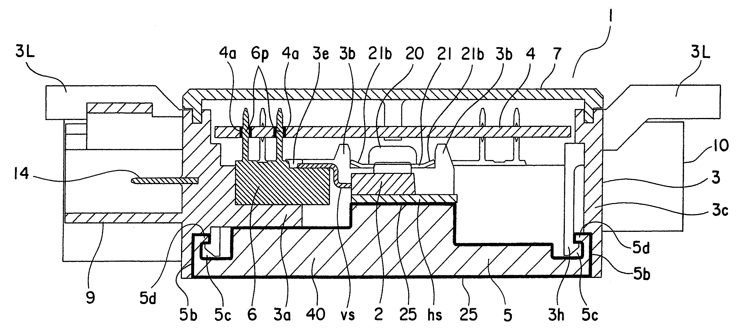
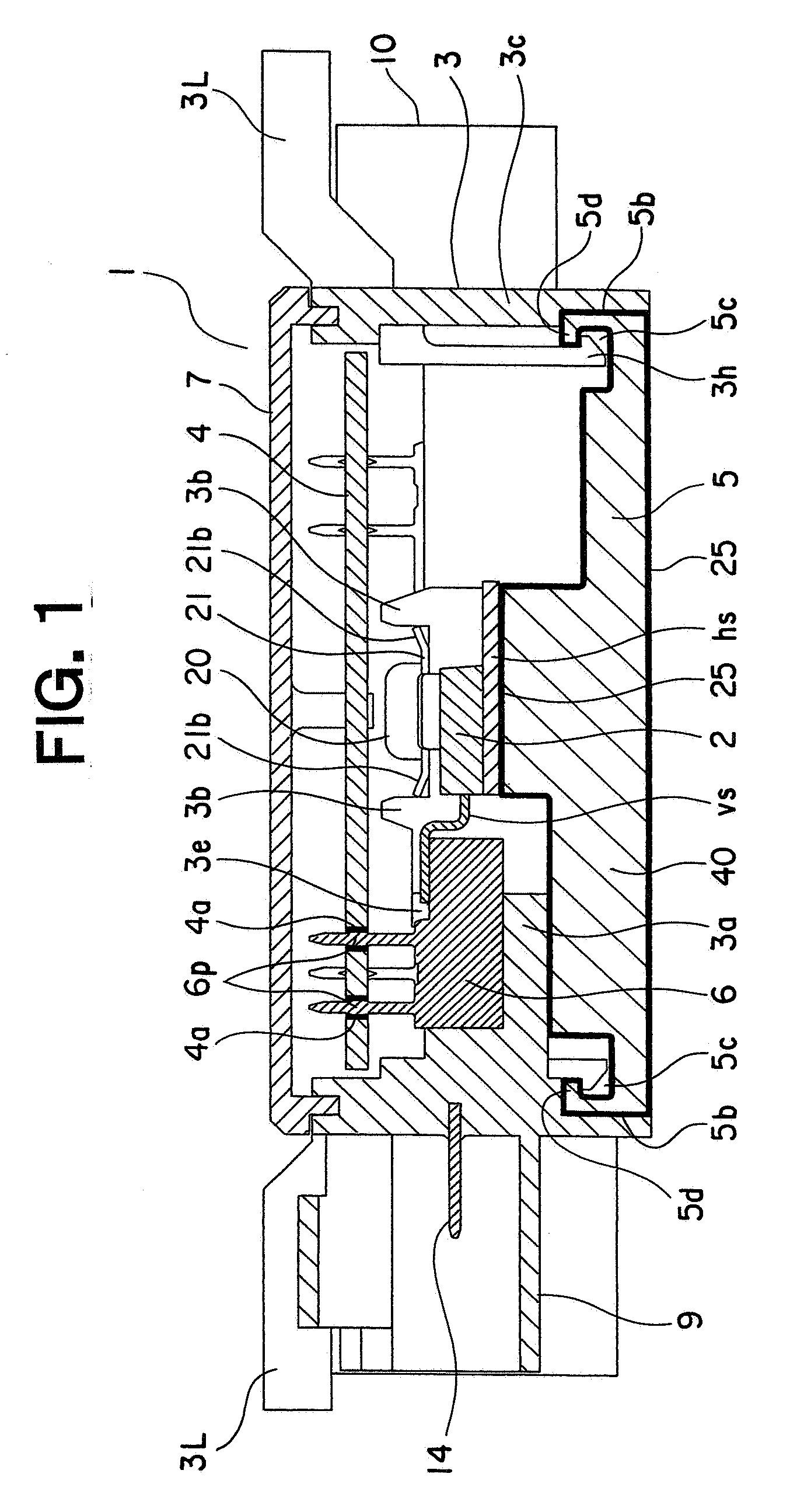
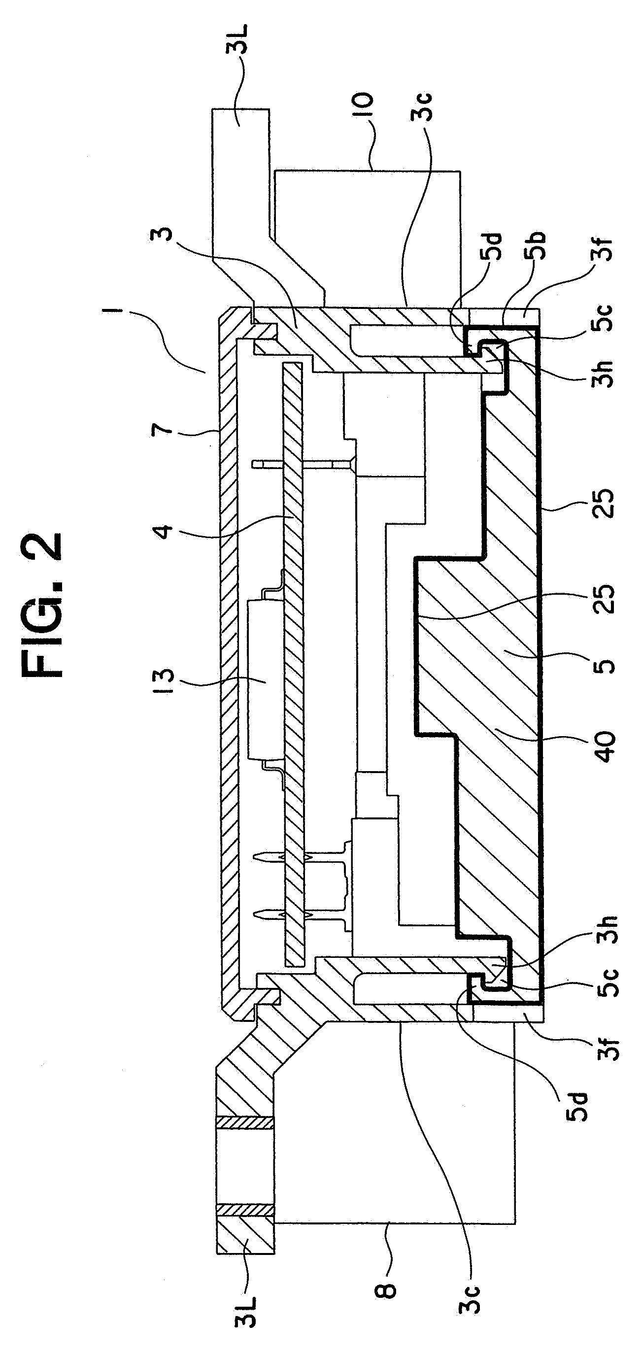
[0020]Referring to the drawings and first to FIG. 1, there is shown, in cross section, an electronic control apparatus according to a first embodiment of the present invention. FIG. 2 is a cross sectional view of the electronic control apparatus when cut in parallel to a cross sectional surface of FIG. 1, and FIG. 3 is a cross sectional view of the electronic control apparatus when cut in a direction perpendicular to the cross sectional surface of FIG. 1. FIG. 4 is an exploded perspective view that shows the electronic control apparatus in FIG. 1, and FIG. 5 is a block diagram that shows an electric power steering system in FIG. 1.

[0021]The electronic control apparatus, generally designated at 1, includes a housing 3 of a box shape that has a pair of opening portions at opposite sides thereof, respectively, a heat sink 5 that is made of aluminum and attached to one of the opening portions in the housing 3, a pair of semiconductor switching elements 2 that are mounted on the heat sin...

embodiment 2

[0086]FIG. 6 is a cross sectional view that shows an electronic control apparatus according to a second embodiment of the present invention, and FIG. 7 is a cross sectional view of the electronic control apparatus of FIG. 6 when the electronic control apparatus is cut along a direction perpendicular to the cross section of FIG. 6.

[0087]In this second embodiment, the construction of the electronic control apparatus, generally designated at 1, is the same as that of the above-mentioned first embodiment except for the housing 3.

[0088]That is, in this second embodiment, grooves 30 are formed between the outer peripheral end faces 5b and the cut surfaces 5a of the heat sink 5 and the inner wall surfaces 3d of the housing 3 at one of the opening portions thereof, and an adhesive or bonding resin in the form of a silicon bonding material 31 is filled into the grooves 30. In addition, the vehicle connector 8, the motor connector 9 and the sensor connector 10 of the first embodiment are chan...


PUM


Abstract

An electronic control apparatus can be reduced in size and cost by removing a metal substrate part. The apparatus includes a housing having a pair of opening portions at its opposite sides, a heat sink attached to one of the opening portions of the housing, a pair of semiconductor switching elements mounted on the heat sink, a circuit board arranged in opposition to the heat sink, a plurality of conductive plates electrically connecting the circuit board and the semiconductor switching elements to each other, and a plate spring urging the semiconductor switching elements against the heat sink. The plate spring has engagement portions press-fitted to and engaged with inner sides of holding portions which are formed on the housing, and the housing has engagement portions engaged with protruded portions of the heat sink.

Description

BACKGROUND OF THE INVENTION[0001]1. Field of the Invention[0002]The present invention relates to an electronic control apparatus used in an electric power steering system for providing an assist force to a steering system of a vehicle by means of the rotational force of an electric motor.[0003]2. Description of the Related Art[0004]In the past, there has been known an electronic control apparatus in which a semiconductor switching element (FET), being a power device, is mounted on a metal substrate, and at the same time, a connecting member for electrically connecting between the metal substrate and parts outside thereof is mounted on the metal substrate.[0005]For example, an electronic control apparatus as described in a first patent document (Japanese patent No. 3644835) includes a metal substrate on which a bridge circuit comprising semiconductor switching elements are mounted for switching a current supplied to an electric motor, a housing with conductive plates, etc., insert mo...

Claims


Application Information

Patent Timeline
IPC IPC(8): H05K7/20B62D5/04
CPCB62D5/0406H05K7/2049H05K7/20854H01L2924/0002H01L2924/00B62D5/04B62D6/00B60R16/02
Inventor TOMINAGA, TSUTOMUKIFUKU, TAKAYUKIAKIYAMA, SHUZOFUJIMOTO, TADAYUKI
Owner MITSUBISHI ELECTRIC CORP
Why Eureka
Try Eureka