Tape Cassette and Tape Printing Apparatus

a printing apparatus and cassette technology, applied in the field of cassettes, can solve the problems of blurred or disabled printing, user cannot confirm whether or not all print data can be printed, etc., and achieve the effect of high quality and high quality

Active Publication Date: 2008-11-13
BROTHER KOGYO KK
View PDF7 Cites 12 Cited by
  • Summary
  • Abstract
  • Description
  • Claims
  • Application Information

AI Technical Summary

Benefits of technology

[0012]In the tape cassette of the present invention, the wireless information circuit elements are disposed at a predetermined pitch in the longitudinal direction of a printing object tape which is wound around the tape spool. The sensor marks are formed at the same pitch as the predetermined pitch of the respective wireless information circuit elements in the longitudinal direction of one side face of this printing object tape. Further, the print areas are provided at the same pitch as the predetermined pitch at a portion excluding the wireless information circuit element between the sensor marks of the printing object tape. Then, the sensor mark, the wireless information circuit element and the print area are provided apart from one another at a predetermined distance repeatedly in the longitudinal direction of the printing object tape. The tape cassette main body is provided with a cassette information specifying means for specifying predetermined cassette information concerning the tape cassette. Then, this cassette information includes a print area information constituted of a distance data indicating a relative distance between the front end portion in the feeding direction of each print area and the sensor mark disposed immediately before on the upstream side in the tape feeding direction of the print area and a length data indicating the length in the feeding direction of the print area.
[0013]Consequently, the distance data indicating the relative distance between the front end portion in the feeding direction of the print area and the sensor mark disposed immediately before on the upstream side in the tape feeding direction of the print area and the length data indicating the length in the feeding direction of the print area can be obtained through this cassette information specifying means, so that the print areas provided at the same pitch as the predetermined pitch, excluding the wireless information circuit element between the respective sensor marks of the printing object tape can be printed accurately, thereby preventing the convex portion including the wireless information circuit element of the printing object tape from being printed and producing a high quality printed label tape.
[0014]Because in the tape cassette of the present invention, the circuit element position information indicating the relative distance between the wireless information circuit element and the sensor mark disposed immediately before on the upstream side in the tape feeding direction of the wireless information circuit element can be obtained through the cassette information specifying means, an arrangement position of the wireless information circuit element on the upstream side in the feeding direction can be specified with respect to the sensor mark, thereby preventing the convex portion including the wireless information circuit element of the printing object tape from being printed securely and producing a high quality printed label tape.
[0015]In the tape printing apparatus of the present invention, the tape cassette is loaded detachably. In this tape cassette, the wireless information circuit elements are disposed at a predetermined pitch in the longitudinal direction of the printing object tape wound around the tape spool. Further, the sensor marks are formed at the same pitch as the predetermined pitch of the wireless information circuit elements in the longitudinal direction of one side face of this printing object tape. The print areas are provided at the same pitch as the predetermined pitch at the portion excluding the wireless information circuit element between the sensor marks of the printing object tape. Then, the sensor marks, the wireless information circuit elements and the print areas are provided a predetermined distance apart from one another repeatedly in the longitudinal direction of the printing object tape. The tape cassette main body is provided with the cassette information specifying means for specifying the predetermined cassette information concerning the tape cassette. This cassette information includes a print area information constituted of a distance data indicating the relative distance between the front end portion in the feeding direction of the print area and the sensor mark disposed immediately before on the upstream side in the tape feeding direction of the print area and the length data indicating the length in the feeding direction of the print area.
[0016]A thermal head is disposed at a position a predetermined first distance apart from the detection sensor on the upstream side in the tape feeding direction for detecting the sensor mark of the printed tape. A cutting means is disposed at a position a predetermined second distance, which is smaller than the predetermined first distance, apart from this detection sensor on the upstream side in the tape feeding direction. Further, the cassette information reading means for reading a predetermined cassette information in cooperation with the cassette information specifying means provided on the tape cassette main body is provided. Then, the tape printing apparatus reads a print area information from the cassette information specifying means provided on the tape cassette through the cassette information reading means. Subsequently, the tape printing apparatus creates a virtual tape indicating the print area on the printing object tape based on the distance data indicating the relative distance between the front end portion in the feeding direction of the print area and the sensor mark disposed immediately before on the upstream side in the tape feeding direction of the print area and the length data indicating the length in the feeding direction of the print area, constituting the print area information, displays it on a display means and displays a condition in which the print data inputted through an input means is printed in the print area.
[0017]Consequently, a user can input the print data while confirming the print area excluding the wireless information circuit element of the virtual tape, so that he or she can input the print data which can be printed in the print area excluding the wireless information circuit element of the printing object tape. Further, the convex portion including the wireless information circuit element of the printing object tape can be prevented from being printed, thereby making it possible to product a high quality printed label tape. Even if the printing object tape is fed by the first distance after the sensor mark of the printing object tape is detected and the margin at the front end portion is cut off, the entire print area can be left securely in the printed tape.

Problems solved by technology

However, in the above-mentioned conventional tape printing apparatus, the print head is positioned at the print starting position with respect to a predetermined format and thus, there exists such a problem that a user cannot confirm whether or not all print data can be printed within a print area of the predetermined format unless he or she tries to print once.
If wireless information circuit elements each having an IC circuit portion which stores predetermined information and an IC circuit antenna connected to the IC circuit portion for transmitting and receiving information are provided at a predetermined pitch in the longitudinal direction of the printing object tape, a portion including this wireless information circuit element is constructed in a convex shape and thus, there exists a problem that if that portion is printed, the print is blurred or disabled.

Method used


Image

  • Tape Cassette and Tape Printing Apparatus
  • Tape Cassette and Tape Printing Apparatus
  • Tape Cassette and Tape Printing Apparatus

Examples


embodiment

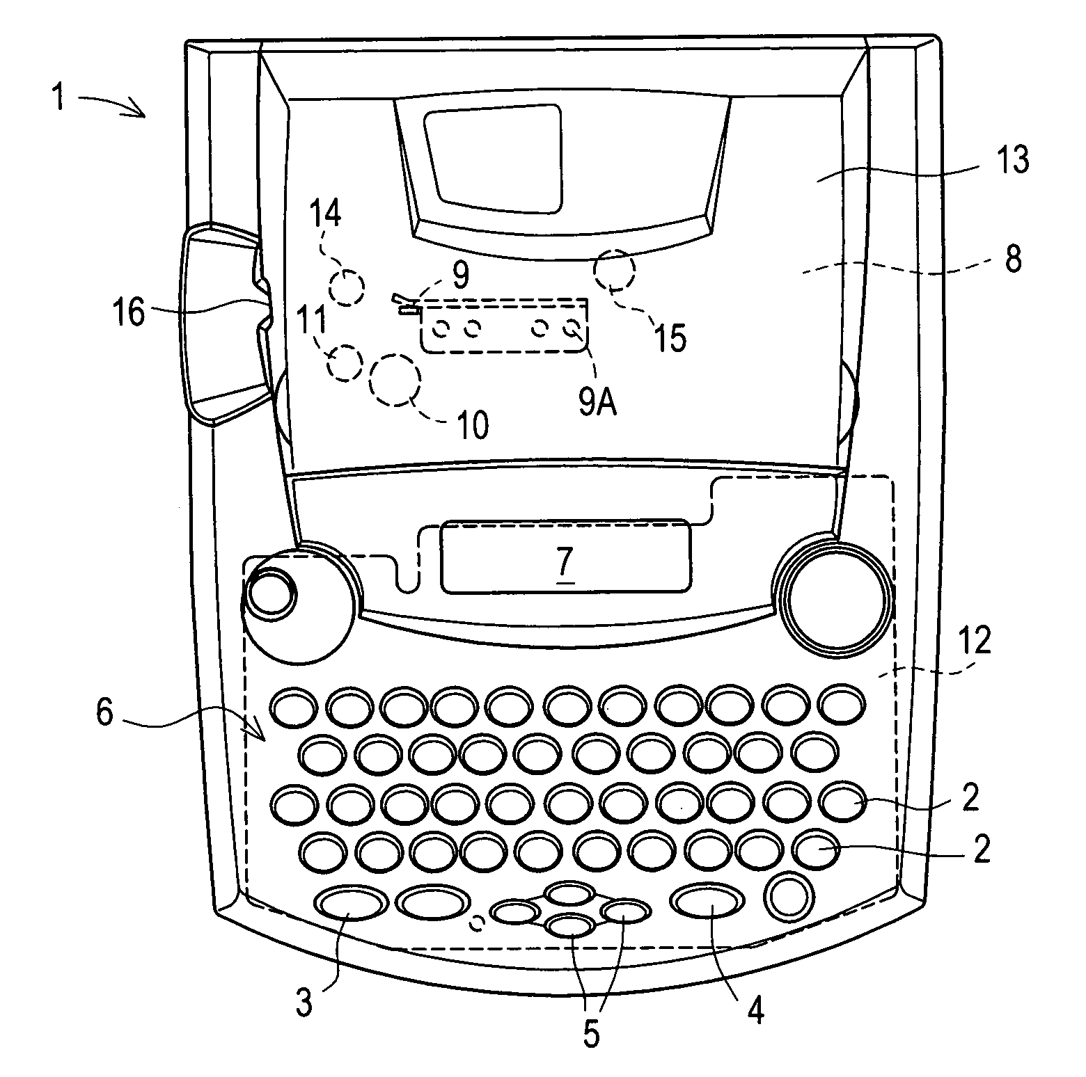
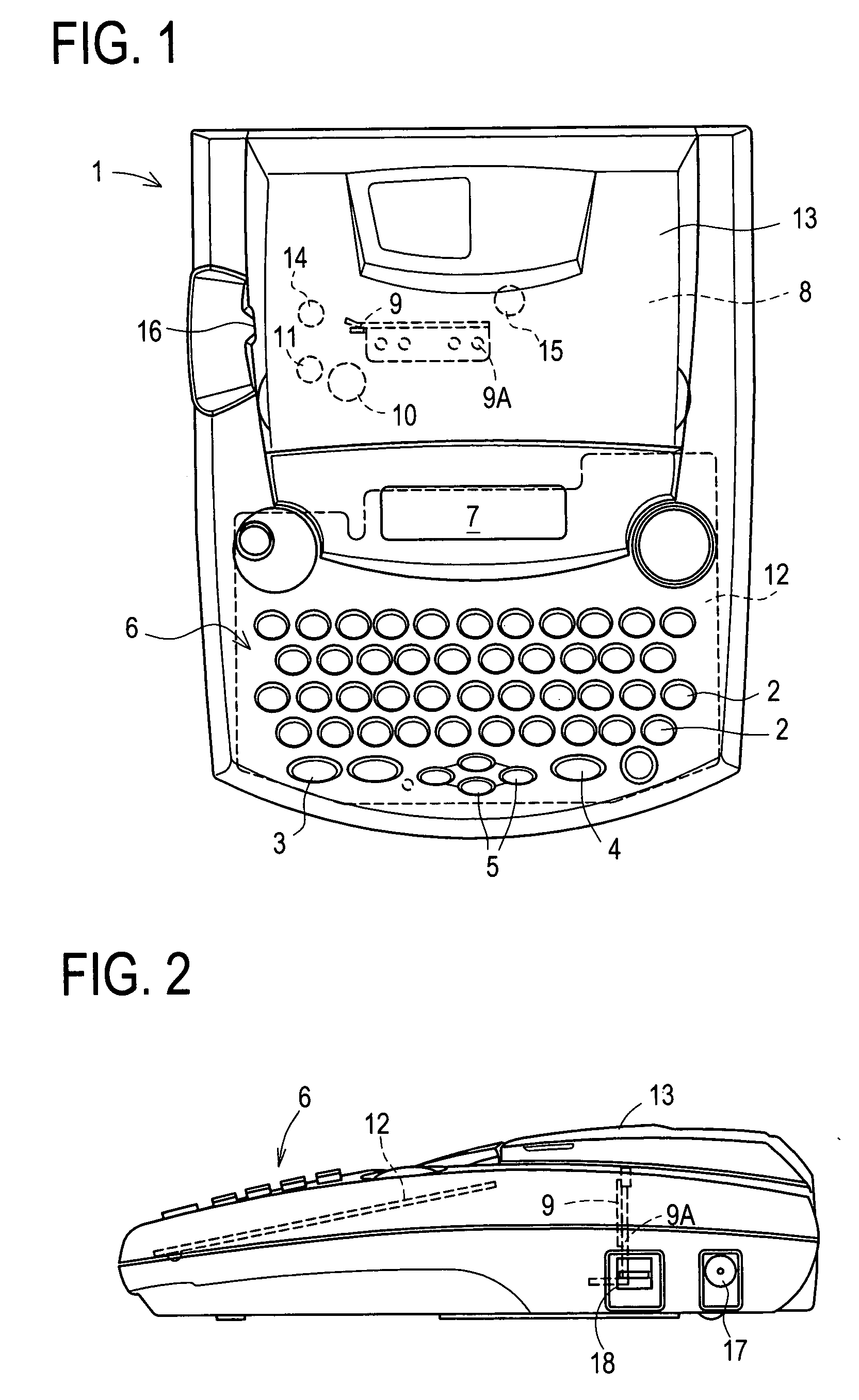
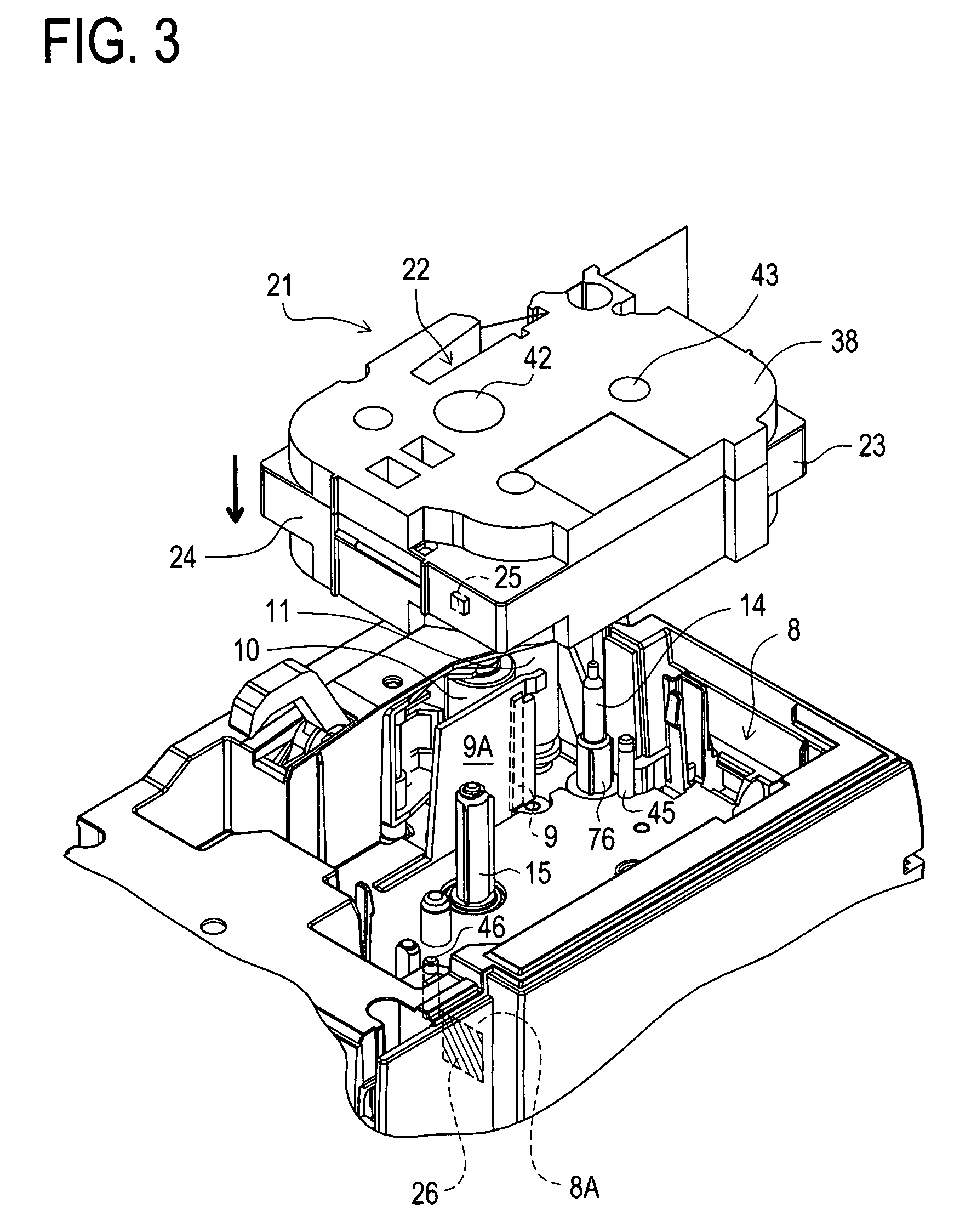
[0118]First, the schematic structure of the tape printing apparatus of this embodiment will be described with reference to FIGS. 1 to 4.

[0119]As shown in FIGS. 1 to 3, in the tape printing apparatus 1 of this embodiment, a keyboard 6 provided with character input keys 2 for creating a text composed of document data, a print key 3 for instructing printing of the text or the like, a return key 4 which executes a line feed instruction and various processings and instructs a selection, and cursor keys 5 for moving a cursor up and down and to the right and left on a liquid crystal display (LCD) 7 which displays characters such as letters over a plurality of lines, and a cassette accommodating portion 8 for accommodating the tape cassette 21, which is covered with an accommodating cover 13, are disposed. A control board 12 in which a control circuit portion is constituted is disposed under the keyboard 6. A label discharge port 16 from which a printed tape is discharged is formed in the l...


PUM


Abstract

A CPU 81 displays a virtual tape 201 of a length obtained by subtracting a length (l1+l2) from an antenna 33 to a thermal head 9 from a data value of an “IC chip pitch length L” when it determines that a printing object tape 531 of type 1 is accommodated in a tape cassette 21. A “tape width” is displayed on the right side of the virtual tape 201. A tape length of the virtual tape 201 is displayed below it. A “tape type” is displayed below it. Then, the CPU 81 displays a print area 202 on the virtual tape 201 from a data value of the “print area” while a right side portion thereof serves as a non-print area. It displays the print data inputted into the print area 202 and waits for the return key 4 to be pressed.

Description

TECHNICAL FIELD[0001]The present invention relates to a tape cassette which accommodates a long tape and a tape printing apparatus comprising a tape feeding means for feeding a tape and a printing means for printing on the tape with the tape cassette loaded thereon detachably.BACKGROUND ART[0002]Conventionally, various tape printing apparatuses have been proposed which comprises a tape cassette accommodating a long tape, a tape feeding means for feeding this tape and a tape printing apparatus for printing on the tape, such that the tape cassette can be loaded detachably.[0003]As the tape printing apparatus which contains a print head and has a printing means for printing data of a given text to a tape as a print medium, for example, there has been known a tape printing apparatus including a mark which is printed on the tape together with a predetermined format and serves as a reference for positioning the print head at a print starting position with respect to the format, and a cont...

Claims


Application Information

Patent Timeline
Patent Type & Authority Applications(United States)
IPC IPC(8): B41J15/00
CPCB41J3/4075B41J3/44B41J11/009B41J11/46B41J15/044B41J21/16
Inventor YAMAGUCHI, KOSHIROITO, AKIRAMIWA, TAKAHIROKUNIEDA, YOSHIOFUJIKAWA, TOSHIHIDE
Owner BROTHER KOGYO KK
Why Eureka
Try Eureka