
Portable pneumatic abdominal aortic tourniquet

a pneumatic aortic and abdominal aorta technology, applied in the field of tourniquets, can solve the problems of ineffective broad application of force to reduce or occlude blood flow through the descending aorta, failure to show or disclose a pneumatic tourniquet, and inability to address the problem in the prior ar

Active Publication Date: 2008-11-13
COMPRESSION WORKS
View PDF30 Cites 90 Cited by
  • Summary
  • Abstract
  • Description
  • Claims
  • Application Information

AI Technical Summary

Benefits of technology

[0018]In a further embodiment, the tourniquet includes a protective bladder sleeve surrounding the directed air bladder in both the inflated and collapsed conditions to resist puncture and protect against environmental exposure of the directed air bladder. Preferably, the protective bladder sleeve is attached to the directed air bladder so that the protective bladder sleeve is collapsed against the directed air bladder when the directed air bladder is in the deflated condition.

Problems solved by technology

However, the prior art does not address the problems associated with abdominal aortic compression in the field in a rapid application portable package for restricting blood flow for a non-compressible arterial hemorrhage in the abdominal region.
One of the major obstacles to providing an effective portable abdominal aortic tourniquet is in providing a focused compression force over a designated area on the abdomen.
Such a broad application of force is ineffective to reduce or occlude blood flow through the descending aorta proximal to the bifurcation in the abdomen due to the deep location of the aorta in the body.
The prior art fails to show or disclose a pneumatic tourniquet having a directed air bladder able to focus the compression force of the tourniquet sufficient to operate as an abdominal aortic tourniquet.
There is no teaching in the patent that this device would be effectively useable as an abdominal aortic tourniquet.
This tourniquet is representative of a vast majority of pneumatic prior art tourniquet devices which completely fail to address the specific problems associated with providing an effective abdominal aortic tourniquet
Again, such devices fail to provide the directed compression force required to restrict blood flow through the descending aorta.

Method used


Image

  • Portable pneumatic abdominal aortic tourniquet
  • Portable pneumatic abdominal aortic tourniquet
  • Portable pneumatic abdominal aortic tourniquet

Examples


Embodiment Construction

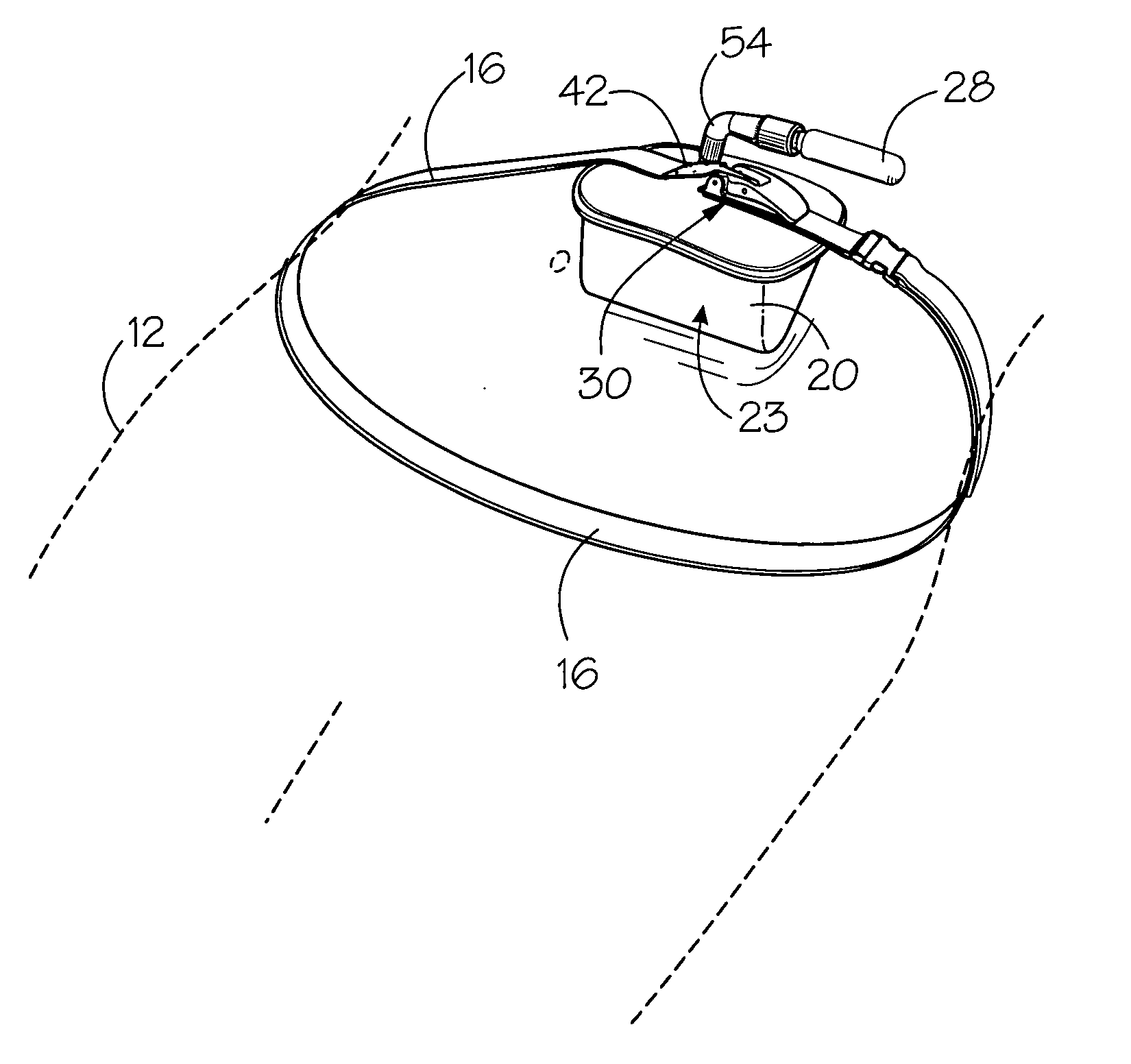
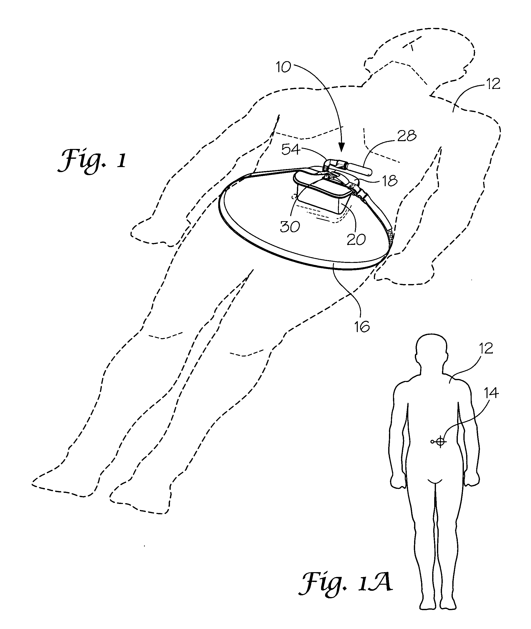
[0038]With reference to the drawings, the invention will now be described in more detail. Referring to FIG. 1, a pneumatic abdominal aortic tourniquet, designated generally as 10, is shown secured around the lower abdomen of a person 12 for restricting blood flow through the descending aorta proximal to the bifurcation to deal with a non-compressible arterial hemorrhage in the abdominal region. Referring to FIG. 1A, the tourniquet is arranged over the abdomen to apply localized pressure to pressure point 14 to restrict blood flow.

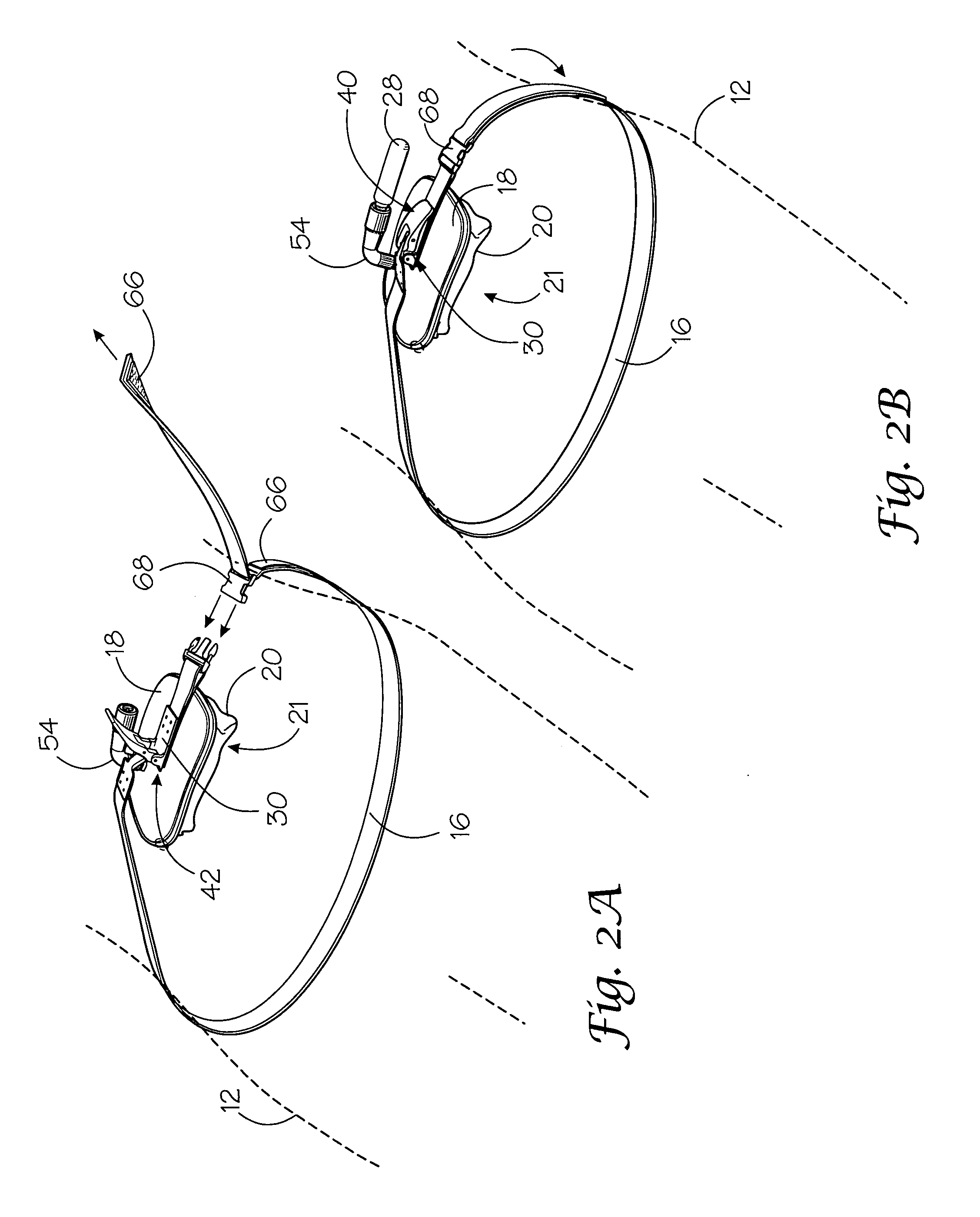
[0039]Referring to FIGS. 1 and 3, pneumatic abdominal aortic tourniquet 10 includes an adjustable waist strap 16 for securing around the abdomen. A rigid base plate 18 is carried on waist strap 16. Base plate 18 is constructed and arranged to have a width greater than waist strap 16 so that base plate 18 extends laterally outward from waist strap 16 to provide a stable base for positioning over a selected area, such as pressure point 14 (FIG. 1A), of the ab...


PUM


Abstract

A portable pneumatic abdominal aortic tourniquet for occlusion of the abdominal descending aorta to restrict blood supply to a non-compressible arterial hemorrhage in the abdominal region. The tourniquet comprising an adjustable waist strap for securing around an abdomen; a directed air bladder mounted to the waist strap having a generally “V” shaped construction operable between a deflated condition wherein the directed air bladder is collapsed, and an inflated condition wherein the directed air bladder is expanded for exerting pressure against the abdomen; and, an air source connected to the directed air bladder for operating the directed air bladder between the deflated condition and the inflated condition.

Description

CROSS REFERENCE TO RELATED APPLICATION[0001]This application claims priority from U.S. Provisional Application 60 / 915,642 filed May 2, 2007.BACKGROUND OF THE INVENTION[0002]1) Field of the Invention[0003]The present invention relates to tourniquets, and more particularly, to a portable pneumatically operated aortic tourniquet device that consists of a waistband and an inflatable air bladder in combination with either a manual pump or a compressed gas injection cartridge for inflating the bladder. The air bladder is of a triangular shape so that a directed compression force is applied to the abdomen specifically to cut-off blood flow to the abdominal descending aorta.[0004]2) Description of Related Art[0005]The prior art is replete with various tourniquet devices that use a wide variety of clamping and / or pneumatic means to apply pressure to various limbs on the body. However, the prior art does not address the problems associated with abdominal aortic compression in the field in a r...

Claims


Application Information

Patent Timeline
Patent Type & Authority Applications(United States)
IPC IPC(8): A61B17/135
CPCA61B17/135A61B17/1325
Inventor CROUSHORN, JOHNSCHWARTZ, RICHARD
Owner COMPRESSION WORKS
Learn More