Flow testing system for fluid networks

a fluid network and flow testing technology, applied in hydrodynamic testing, liquid/fluent solid measurement, instruments, etc., can solve problems such as contamination, collapse of water mains, and system detrimental effects, and achieve high-automatic and accurate methods

Active Publication Date: 2008-11-13
HURCO TECH
View PDF47 Cites 93 Cited by
  • Summary
  • Abstract
  • Description
  • Claims
  • Application Information

AI Technical Summary

Benefits of technology

[0057]One significant advantage of the present invention is the provision of a system for conducting flow testing of a hydrant on the water supply system by a single person in a highly automated and accurate manner with the components of the device wirelessly communicating with each other. Moreover, the another advantage of the new apparatus, kit, system and method described herein is that it may be advantageously used for coefficient factor (C-Factor) testing to determine the resistance to the flow of fluid in a pipe system such as a water main. In applying such testing to water mains, the test can cover several city blocks and by pass several valves or hydrants. Yet C-Factor testing includes the determining a residual pressure, the determination of flow at a flow hydrant (the...

Problems solved by technology

Additionally, the use of fire fighting equipment to draw water from the hydrant using a pump can increase the flow capacity of water from the water supply system, but attempting to pump water from the hydrant in excess of the safe capacity of water available from the hydrant at that point in the supply system can have effects detrimental to the system due to the creation of a negative pressure condition created in the main.
These detrimental effects include triggering a collapse of the water main or the introduction of contaminants into the main through cracks or joints in the pipe.
Such testing can indicate systemic weaknesses such as main clogging, failing water mains such as when residual pressures imposed upon water mains become too high by pulling water from the main at a flow hydrant, and compromised valves.
Testing is typically conducted on a periodic basis, since water supply systems are constantly being affected by changing conditions, including improvements to the system, deterioration of parts of the system, and changes in usage of the system, etc.
However, the procedures of both of these tests are not performed only at the subject hydrant...

Method used


Image

  • Flow testing system for fluid networks
  • Flow testing system for fluid networks
  • Flow testing system for fluid networks

Examples


Embodiment Construction

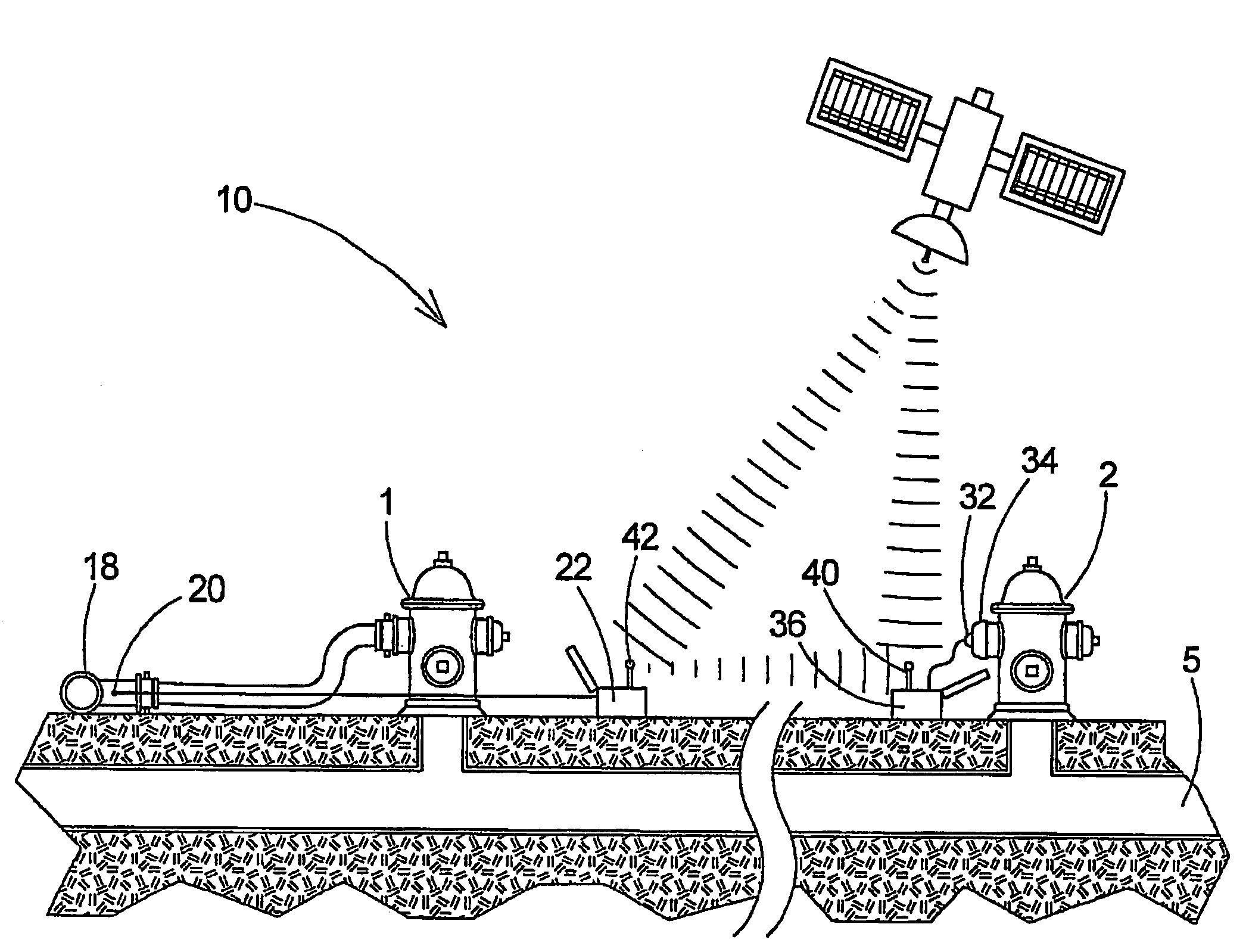
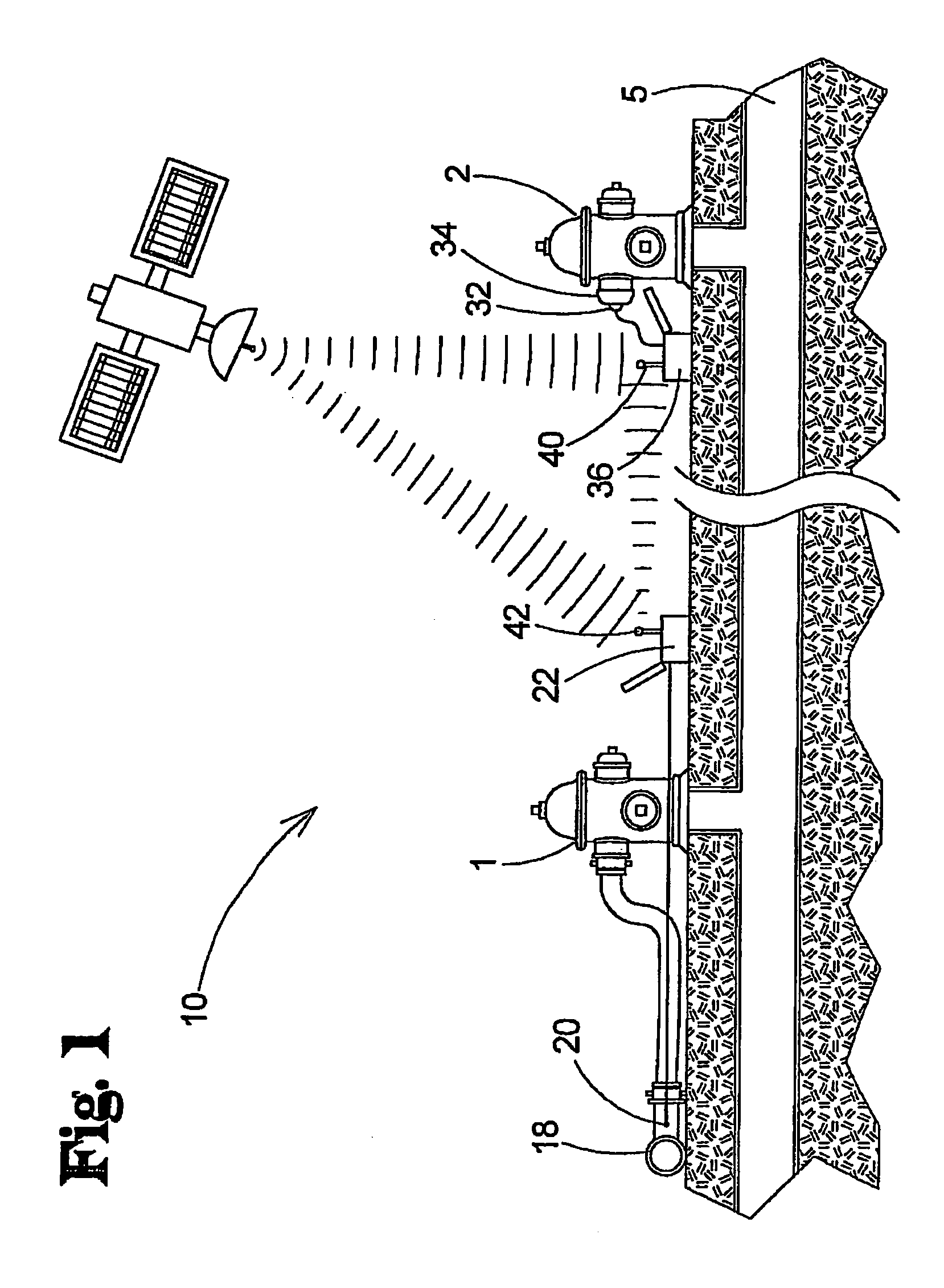
[0067]With reference now to the drawings, and in particular to FIGS. 1 through 7 thereof, a new apparatus, system and method for testing fluid flow and pressures in fluid networks will be described.

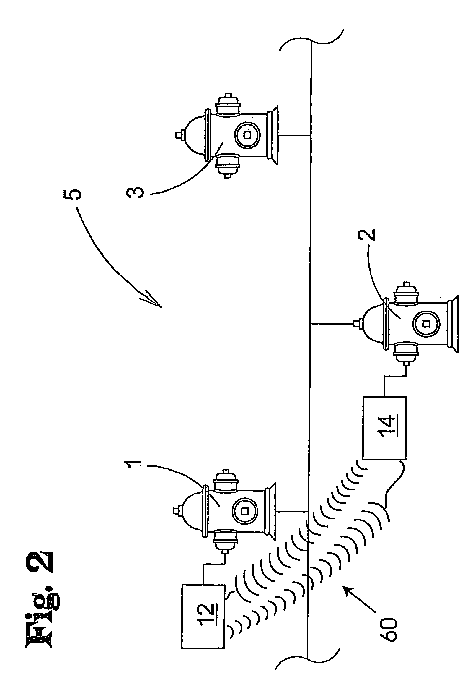
[0068]One aspect of the invention involves a flow testing system 10 (FIG. 1) for conducting a test event for detecting fluid characteristics in a network of fluid-carrying pipes (see FIG. 2). The invention is highly suitable for use on water system 5, such as are maintained by municipalities or water districts, that includes a plurality of outlets (in addition to those provided for customers of the water supply system) for supplying water for, for example, fire fighting and fire suppression. Typically, these fire suppression outlets take the form of hydrants 1 located adjacent to streets of the municipality. Although the use of the flow testing system 10 is not limited to these hydrants 1, the system 10 will be described in terms of use with the hydrants with the understanding that it cou...


PUM


Abstract

An apparatus, system, method and kit for testing fluid flow and pressure is provided. The apparatus, system, method and kit include or include the use of a flow unit which is configured to measure flow rate and/or flow velocity when interfaced with a flow valve or hydrant and a pressure unit configured to measure at least residual pressure when interfaced with a test valve or hydrant. At least one of the units is configured to wirelessly send data transmissions to the other unit which is configured to receive such transmissions.

Description

[0001]This is a continuation-in-part application of application Ser. No. 11 / 800,563, filed May 7, 2007 which is incorporated by reference as if fully rewritten herein.FIELD[0002]The present invention relates to an apparatus, system, method and kit for testing fluid flow and pressure, and more particularly, pertains to flow and pressure testing of fluid networks that permits testing of a valve or hydrant on a water supply system by a single person in a highly automated and accurate manner.BACKGROUND AND DESCRIPTION OF THE PRIOR ART[0003]Fluid supply networks, such as municipal water supply systems, typically test the flow and pressure characteristics of outlets, such as hydrants, on the system to determine the capabilities of the system to deliver an adequate flow of water during high water use events such as the fighting of a fire using water from the supply system.[0004]Not only are these characteristics of the municipal water supply system a concern of the municipality in gauging ...

Claims


Application Information

Patent Timeline
IPC IPC(8): G01F1/34
CPCF17D5/00G01L19/00G01F1/46
Inventor HURLEY, LYNDON J.
Owner HURCO TECH
Why Eureka
Try Eureka