Draining insole for shoes

a technology for insoles and shoes, applied in the direction of uppers, bootlegs, apparel, etc., can solve the problems of wearer's foot, high unhygienic shoes, unpleasant smells, etc., and achieve the effect of providing comfort to the foot and facilitating walking for users

a technology for insoles and shoes, applied in the direction of uppers, bootlegs, apparel, etc., can solve the problems of wearer's foot, high unhygienic shoes, unpleasant smells, etc., and achieve the effect of providing comfort to the foot and facilitating walking for users

US20080282582A1Inactive Publication Date: 2008-11-20MIZRAHI SHAPIRO EDUARDO NURI

Image

  • Draining insole for shoes
  • Draining insole for shoes
  • Draining insole for shoes

Examples


Embodiment Construction

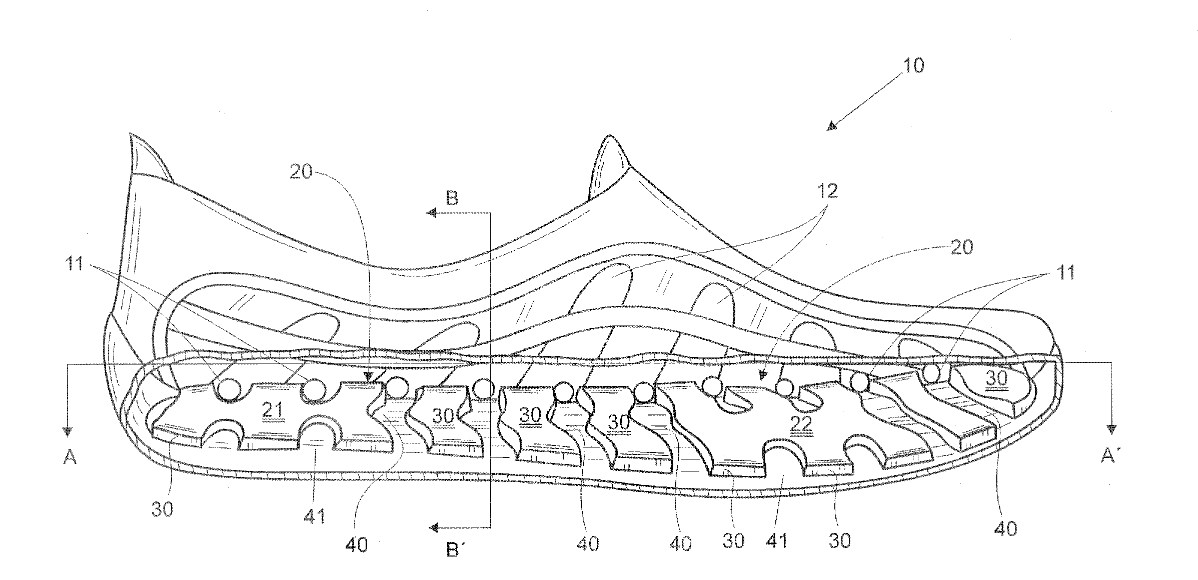
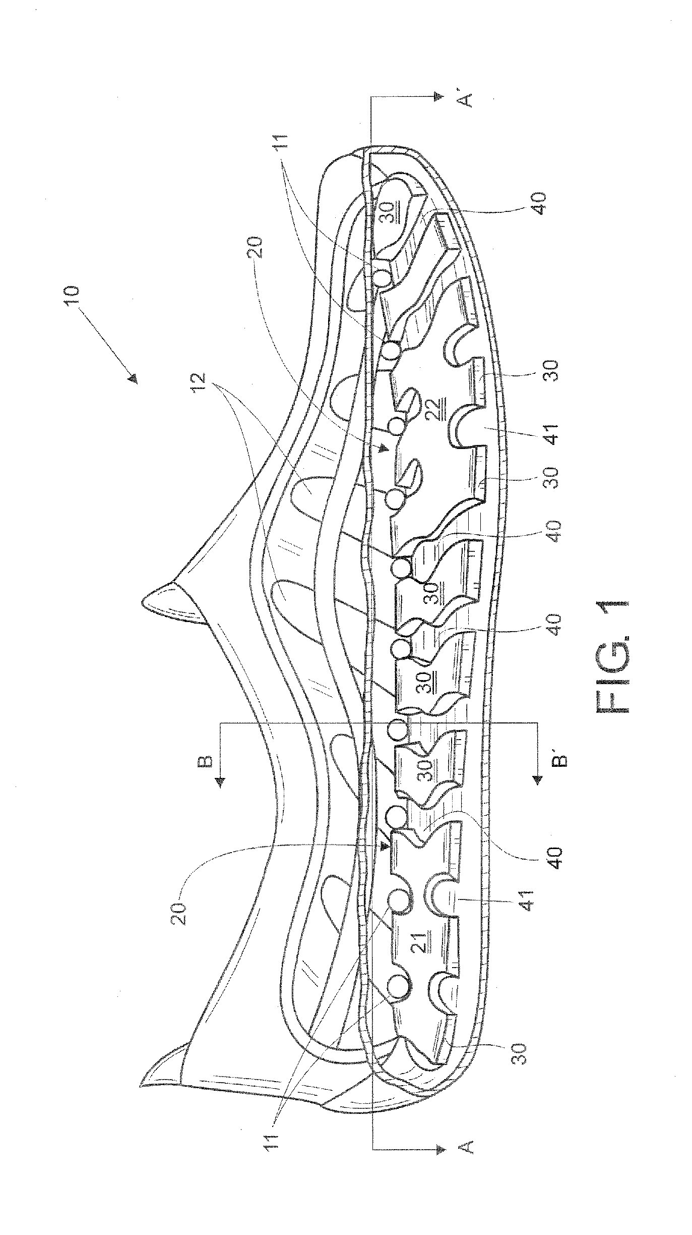
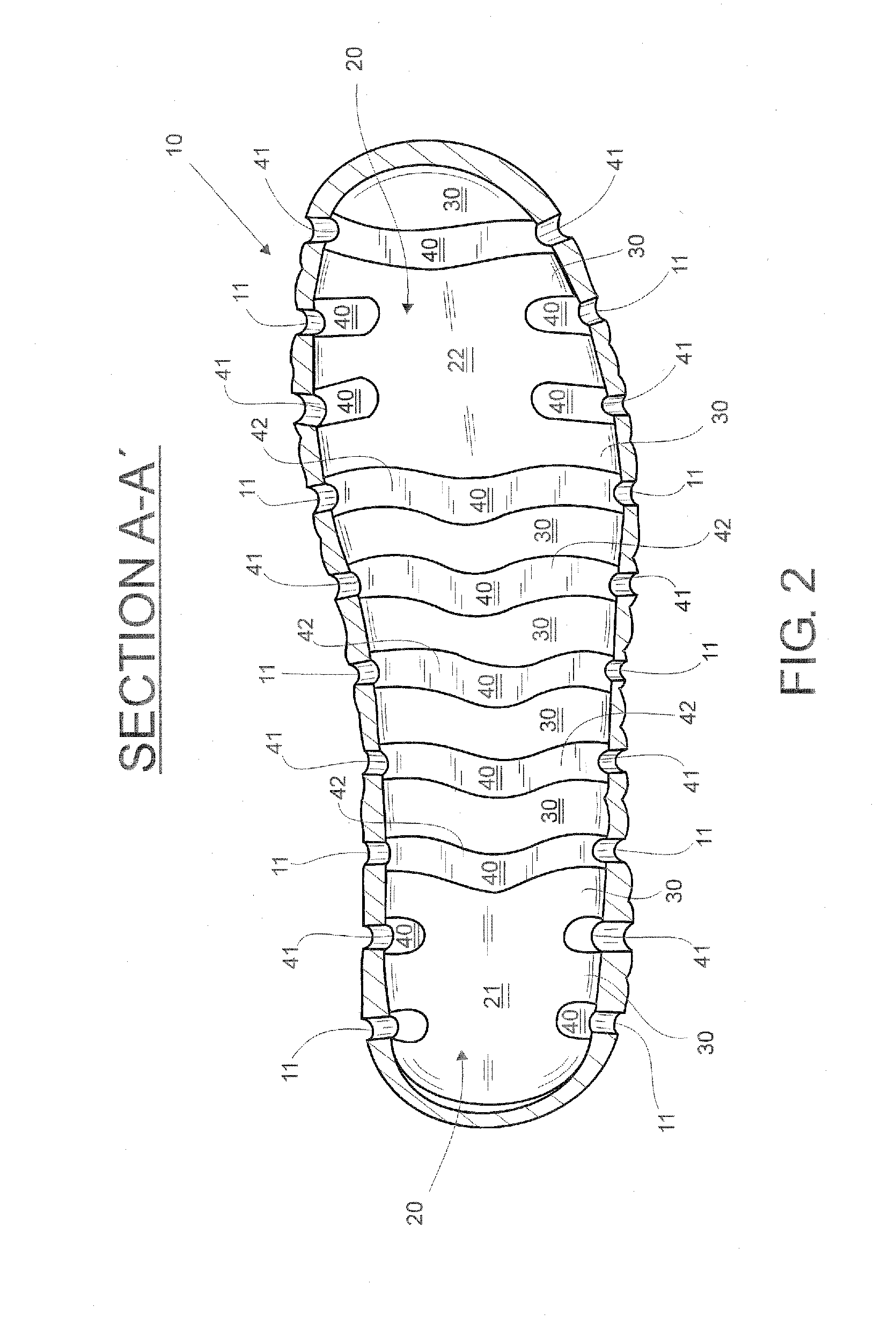
[0019]Referring to FIGS. 1 and 2 of the appended drawings there is shown a shoe 10 in the shape of a diving slipper, with ventilation openings 12 to freshen the instep of the foot. Inside the shoe 10, an insole 20 is embedded therein that is built pursuant to one preferred embodiment of the invention, which is to be deemed for illustrative but not restrictive purposes of the same. In FIG. 1, it is convenient to explain that one part of the shoe 10 has been removed in order to see the insole 20 located therein more clearly. On the other hand, FIG. 2 shows a shoe 10 cut view taken alongside line A-A′ of FIG. 1; that is, it is a view wherein the upper part of the shoe 10 has been removed, leaving only the bottom part thereof in order to view the insole 20 from the top.

[0020]The insole 20 comprises a plurality of bridges 30 projecting from the insole and extending wide-wise of the insole 20 and spaced apart one from each other alongside thereof; a plurality of channels 40, each one of w...


PUM


Abstract

A draining insole for shoes that dislodges foreign objects therein is disclosed; the insole has a plurality of bridges projecting from the insole and with an upper surface on top of which the foot rests; the bridges extending wide-wise of the insole and separately distributed from each other alongside thereof. The insole also includes a plurality of channels, each one of the same separating a bridge from the other; each channel having a pair of open ends and a bottom with a gabled surface. In turn, these bridges are joined at areas where the foot might get hurt; each end of the channel is in fluid communication with one draining hole included in the shoe in order to dislodge foreign matter located at the insole.

Description

FIELD OF THE INVENTION[0001]The present invention relates to the techniques employed in the design and manufacture of shoes and, more specifically, to a draining insole for shoes that is very useful to dislodge foreign matter inside thereof; the insole also promotes ventilation towards the interior of the shoe and thermal insulation of the foot.BACKGROUND OF THE INVENTION[0002]The use of shoes by humans dates back to the rudimentary employment of materials from nature such as woven vegetal fibers and, later on, animal leather. Currently, it can be said that for almost any activity or occasion there exists a shoe specifically designed to meet the particular needs thereof.[0003]For instance, the use of sandals, espadrilles, slippers, huaraches (leather sandals), diving slippers etc. is customary for leisure, rest, beach and diving activities. These shoes are characterized by their constant contact with water, their light weight and their being open to promote foot ventilation, with th...

Claims


Application Information

Patent Timeline
20 Nov 2008
Publication
US20080282582A1
IPC
A43B7/06; A43B13/38
CPC
A43B5/08
Inventors
SHAPIRO, EDUARDO NURI MIZRAHI