Integral facet cryopump, water vapor pump, or high vacuum pump

a cryopump and integrated technology, applied in the direction of positive displacement liquid engine, container discharging method, separation process, etc., can solve the problems of affecting throughput, affecting the overall cost of the cluster tool, and requiring a large number of valves

Active Publication Date: 2008-11-20
EDWARDS VACUUM LLC
View PDF27 Cites 16 Cited by
  • Summary
  • Abstract
  • Description
  • Claims
  • Application Information

AI Technical Summary

Problems solved by technology

Such long recovery times can be detrimental to throughput.
Valve arrangements can be costly.
Numerous sets of valves are costly and can drive up the overall cost of the cluster tool.
Valve control is also costly and may increase the overall operation cost of the cluster tool.
Further, regeneration operations often can result in a suspension of the manufacturing processing to remove materials from a primary pumping surface of a cryogenic pump.
These regeneration operations can also decrease throughput of the cluster tool.

Method used


Image

  • Integral facet cryopump, water vapor pump, or high vacuum pump
  • Integral facet cryopump, water vapor pump, or high vacuum pump
  • Integral facet cryopump, water vapor pump, or high vacuum pump

Examples


Embodiment Construction

[0020]A description of preferred embodiments of the invention follows.

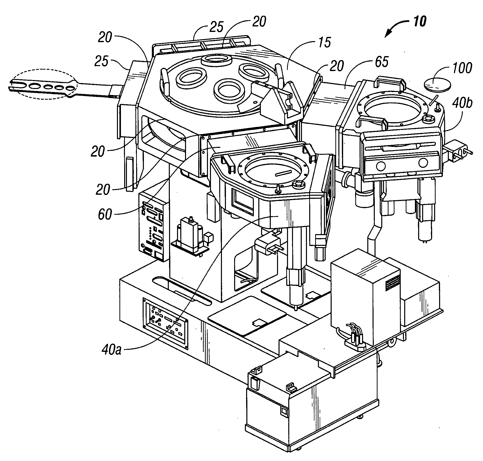
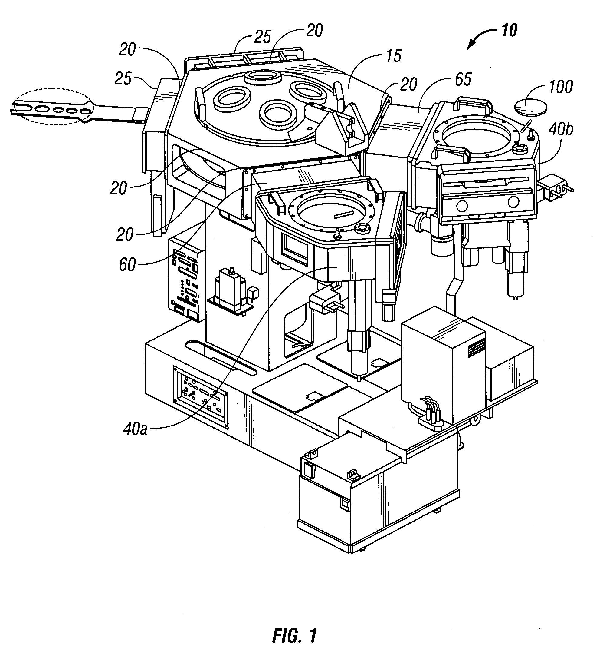
[0021]Turning now to FIG. 1 and 2A, there is shown a first embodiment of the present disclosure of a cluster tool 10 for use in ultrahigh vacuum chemical vapor deposition (“CVD”) manufacturing. The cluster tool 10 includes a transfer chamber 15 including a number of faces 20. Located on an end of the transfer chamber 15 are provisions for mounting a number of process chambers 25 (FIG. 2A). These process chambers 25 mounted to these locations would be configured for performing one or more manufacturing operations on a wafer 100.

[0022]Turning to a top schematic view shown in FIG. 2A, the cluster tool 10 has, disposed in the transfer chamber 15, a wafer handling robot 30. Robot 30 is disposed in a centermost portion of the transfer chamber 15 for automatically transferring a wafer 100 between various chambers. The wafer handling robot 30 is configured to move the wafer 100 from a load lock chamber 40a to the transfer...


PUM

PropertyMeasurementUnit
pressureaaaaaaaaaa
vacuum pressureaaaaaaaaaa
pressureaaaaaaaaaa

Abstract

A cluster tool has a transfer chamber, and a load lock chamber. An adaptor is configured to be coupled between the transfer chamber and the load lock chamber. The adaptor has an adaptor housing with an interior space including an entrance with a first valve and an exit with a second valve. The adaptor housing forms a substrate path through the interior space. The first valve connects the interior space and the load lock chamber. The second valve connects the interior space and the transfer chamber. A cryogenic surface is associated with the adaptor. Other pumps can be associated with the adaptor, such as, for example, a turbo pump, or water vapor pump. The cryogenic surface is configured to selectively evacuate the interior space. A wafer is adapted to be moved through the first valve and through the adaptor housing along the path. The wafer is moved through the exit and into the transfer chamber once the second valve is opened. This adaptor can be applied to the process chamber as well as the load lock.

Description

BACKGROUND OF THE INVENTION[0001]A cluster tool includes processing chambers, internal robots to manipulate wafers, and load lock chambers where wafer exchanges take place from the load lock chamber to the transfer chamber. The transfer chamber is held at a low vacuum pressure. The load lock chamber is connected to the transfer chamber by a valve. The load lock chamber receives a wafer from atmospheric pressure. The vacuum pressure of the transfer chamber / buffer will increase once it is opened to receive a wafer. Thereafter, the transfer chamber will be pumped by a vacuum pump to return to the vacuum pressure.[0002]Sometimes long recovery times may be needed for the transfer chamber to return to the vacuum pressure, once the transfer chamber is closed and receives the wafer from the load lock chamber. Such long recovery times can be detrimental to throughput. A recovery time associated with the transfer chamber / buffer returning to a low vacuum pressure should be conceivably as short...

Claims


Application Information

Patent Timeline
Patent Type & Authority Applications(United States)
IPC IPC(8): F04B37/08
CPCH01L21/67173H01L21/6719
Inventor BARTLETT, ALLEN J.KRAUS, JOSEPH A.EACOBACCI, JR., MICHAEL J.
Owner EDWARDS VACUUM LLC
Why Eureka
Try Eureka