
Solar Cell Module Connector

a solar cell and module technology, applied in the direction of coupling device connection, pv power plant, coupling device details, etc., can solve the problem of erroneous connection between the positive and negative terminals in each group, and achieve the effect of preventing inverse connection

Inactive Publication Date: 2008-11-20
SUMITOMO WIRING SYST LTD
View PDF2 Cites 16 Cited by
  • Summary
  • Abstract
  • Description
  • Claims
  • Application Information

AI Technical Summary

Benefits of technology

[0016]The dipole connectors are connected to ends of cables led out from the pair of positive and negative terminals of each solar cell module, the terminals in the dipole connector disposed on one side of the solar cell module form positive and negative plugs, and the terminals in the dipole connector disposed on the other side of the solar cell module form positive and negative sockets. In a case where a plurality of solar cell modules aligned with each other in row and column directions are connected in parallel with each other to form one group in a horizontal direction for example, the two dipole connectors opposed to each other in the column direction are in a plug-to-plug relationship or in a socket-to-socket relationship. Therefore, the occurrence of erroneous connection between the two dipole connectors between groups can be avoided.
[0024]The offset portions are formed on the basis of a stepped form of the clamp. Therefore, prevention of inverse connection can be achieved without changing the structure of the existing positive and negative connectors.

Problems solved by technology

Therefore, there is a possibility of a connection being erroneously made between the positive and negative terminals in each group as well as between the groups.

Method used


Image

  • Solar Cell Module Connector
  • Solar Cell Module Connector
  • Solar Cell Module Connector

Examples


embodiment 1

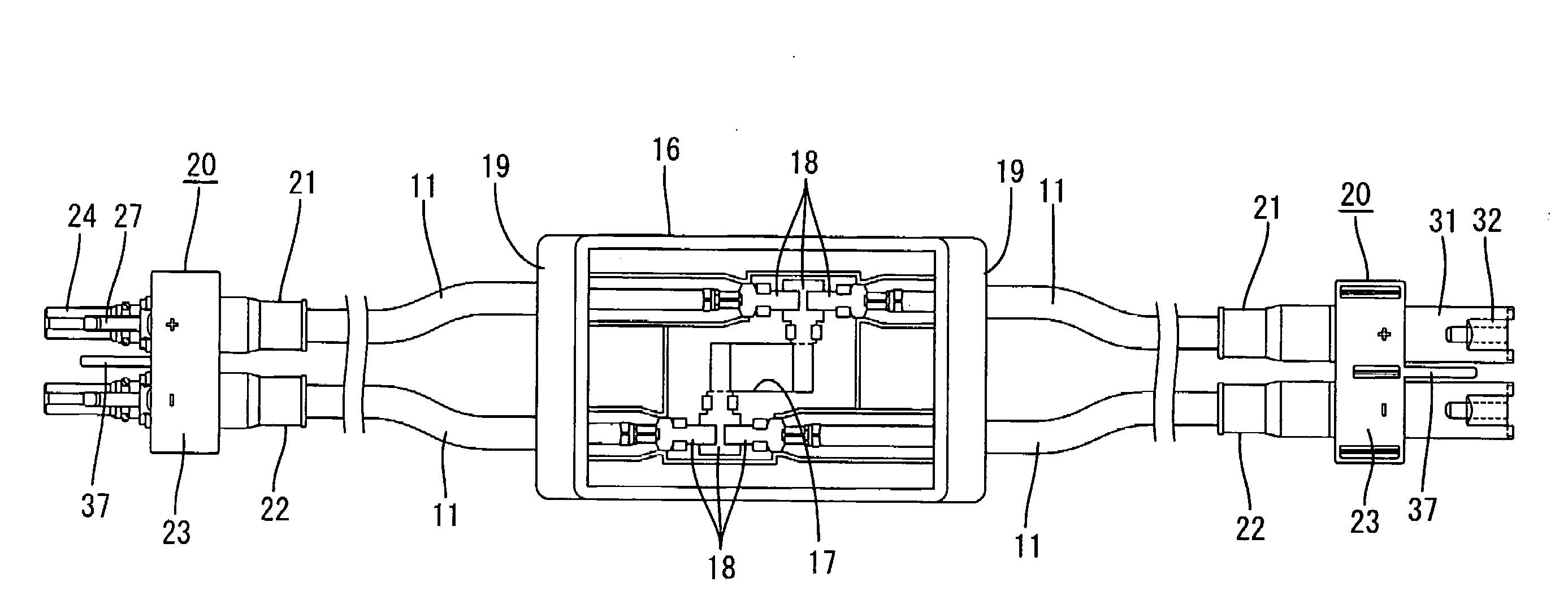
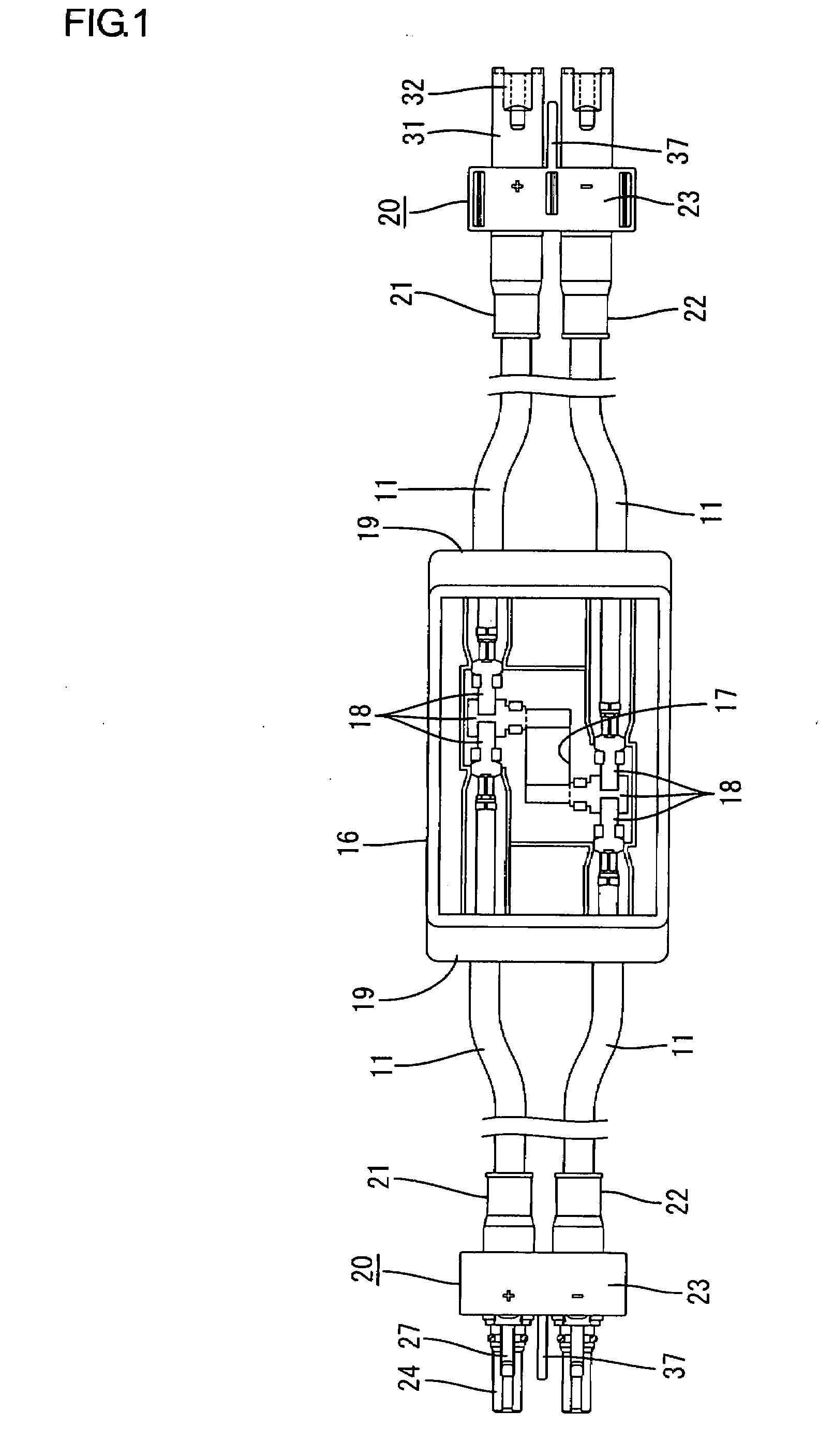
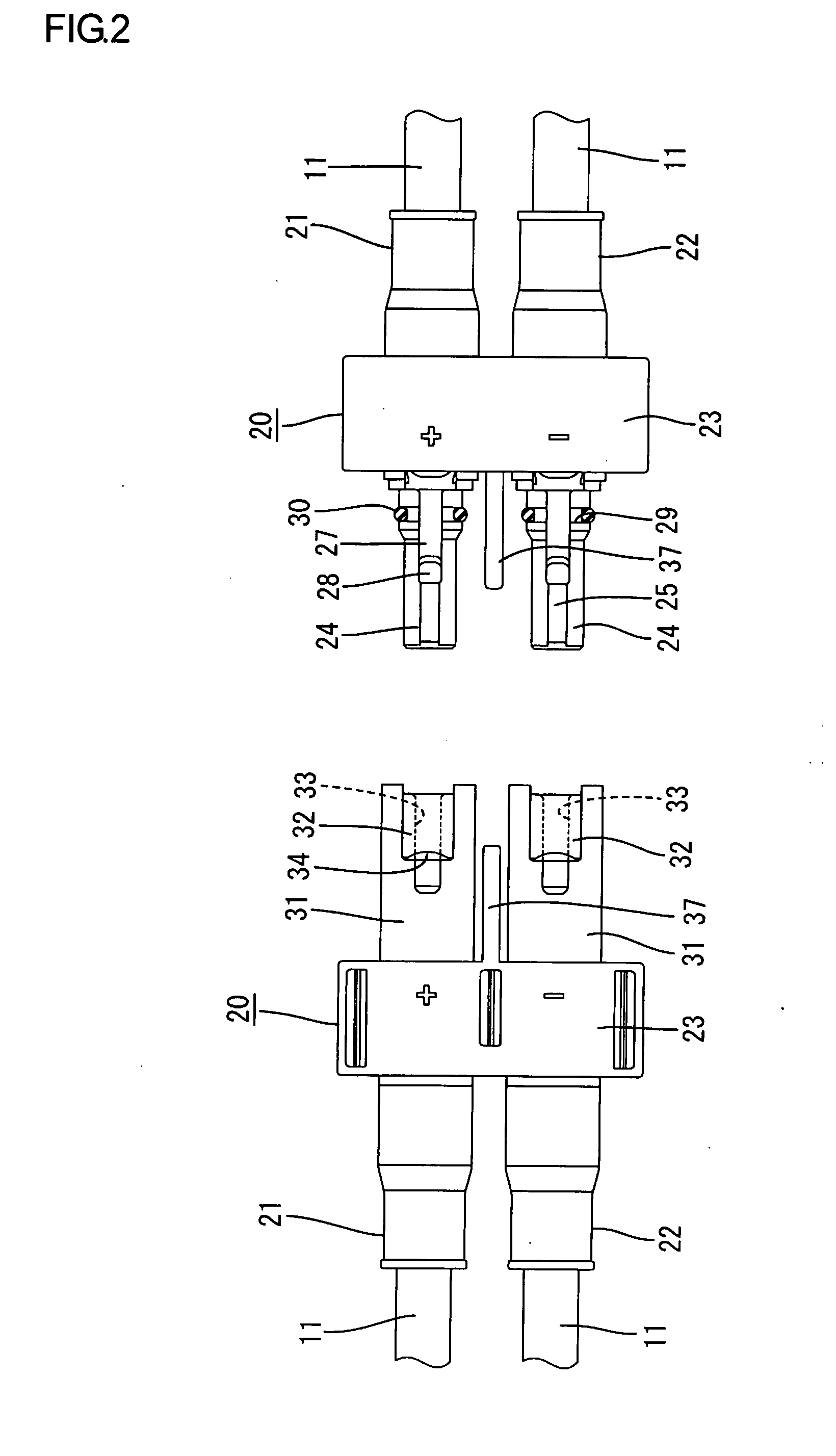
[0054]Embodiment 1 of the present invention will be described with reference to FIGS. 1 to 8. In this embodiment, two pairs of positive and negative cables 11, i.e., one pair of positive and negative cables 11 and another pair of positive and negative cables 11, are led out by dividing a pair of positive and negative terminals from a solar cell module 10, and a dipole connector 20 having terminals 15 connected to ends of the cables 11 led out is integrally formed. A plurality of solar cell modules 10 are disposed in matrix form, i.e., in alignment with each other in row and column directions, and are connected in parallel with each other.

[0055]A terminal box 16 is attached to the back surface (the surface opposite from the glass surface) of the solar cell module 10, as shown in FIG. 1. A pair of positive and negative leads (not shown) from the solar cell module 10 are led into the terminal box 16 through an opening 17. Ends of the leads are connected to pairs of positive and negativ...

embodiment 2

[0070]Embodiment 2 of the present invention will be described with reference to FIGS. 9 to 12. The forms of the dipole connectors 20 in Embodiment 2 differ from those in Embodiment 1. In other respects, Embodiment 2 is substantially the same as Embodiment 1. A redundant description in relation to the description of Embodiment 1 will not be made. Structural portions identical or corresponding to those in Embodiment 1 are indicated by the same reference numerals.

[0071]In Embodiment 2, the forms of the positive connector 21 and the negative connector 22 constituting each dipole connector 20 are made different from each other to prevent inverse connection between the two dipole connectors 20 disposed between each adjacent pair of solar cell modules 10. More specifically, a construction described below is provided. As shown in FIG. 9 on the right-hand side and in FIG. 11, the protuberant portions 26 and the lock portions 27 in Embodiment 1 are formed on the positive connector 21 on the s...

embodiment 3

[0073]Embodiment 3 of the present invention will be described with reference to FIGS. 13 to 16. The form of clamps 23 in the dipole connectors 20 in Embodiment 3 differs from that in Embodiment 1. In other respects, Embodiment 3 is substantially the same as Embodiment 1. Structural portions identical or corresponding to those in Embodiment 1 are indicated by the same reference numerals.

[0074]Embodiment 3 has the same positive connectors 21 and negative connectors 22 as those in Embodiment 1, and pairs of connectors 21 and 22 are fitted in clamps 23 to prevent inverse connection between two dipole connectors 20 disposed between each adjacent pair of solar cell modules 10. That is, as shown in FIG. 13, the clamp 23 on the plug side and the clamp 23 on the socket side in the clamps 23 in Embodiment 3 are identical to each other, and each clamp 23 has a holding portion 41 on the positive connector 21 side for holding the positive connector 21, and a holding portion 42 on the negative co...


PUM


Abstract

The present invention includes two pairs of positive and negative cables are led out by dividing a pair of positive and negative terminals of a solar cell modules, and dipole connectors to which terminals are connected are formed on ends of the cables. The terminals in the dipole connector disposed on one side of the solar cell module form positive and negative plugs, while the terminals in the other dipole connector disposed on the other side of the solar cell module form positive and negative sockets. The cables include an inverse connection preventing portion which allows connection between the dipole connectors on a plug and socket side disposed between each adjacent solar cell modules when the polarities of the negative and positive terminals are the same, but which restricts connection therebetween when the polarities of the negative and positive terminals differ from each other.

Description

TECHNICAL FIELD[0001]The present invention relates to a solar cell module connector used to connect a plurality of solar cell modules.BACKGROUND ART[0002]A solar power generation system supplies direct currents from a solar cell panel installed on a house roof to electric appliances via a device such as an inverter. The solar cell panel is constituted by a plurality of solar cell modules which are connected to each other via connectors connected to ends of cables.[0003]A solar power generation system formed by connecting a plurality of solar cell modules in parallel with each other is known (see, for example, patent document 1 shown below). A solar power generation system of this kind has a structure in which, as shown in FIG. 17A, a pair of positive and negative cables 2 and another pair of positive and negative cables 2 diverging from a pair of positive and negative terminals of a solar cell module 1 are led out, positive connectors 3 and negative connectors 4 are attached to ends...

Claims


Application Information

Patent Timeline
Patent Type & Authority Applications(United States)
IPC IPC(8): H01L31/05
CPCH01L31/02008H01R13/6273H02S40/34Y02E10/50H01R13/642
Inventor HIGASHIKOZONO, MAKOTONAITO, KAZUKI
Owner SUMITOMO WIRING SYST LTD
Learn More