Heat Dissipation System With A Plate Evaporator

a technology of heat pipe and evaporator, which is applied in the direction of lighting and heating apparatus, lighting/ventilation/heating modifications, and cooling/ventilation/heating modifications. it can solve the problems of limited cell size of wick structure, limitation of heat pipe length, and barrier in increasing the performance of traditional heat pipes. achieve the effect of small pore size and small pore siz

Active Publication Date: 2008-11-20
IND TECH RES INST
View PDF11 Cites 84 Cited by
  • Summary
  • Abstract
  • Description
  • Claims
  • Application Information

AI Technical Summary

Problems solved by technology

The wick structure of the traditional heat pipe is distributed in the inner surface of all the heat pipe, and the cell size of the wick structure thereof is limited.
This contradictory causes a barrier in increasing the performance of the traditional heat pipe.
Meanwhile, the limitation of the capillary force also causes the limitation of the length of heat pipe.
When the applied heat load or the wall temperature becomes excessively, boiling of the liquid in the wick structure may occur.
The vapor bubbles generated inside the wick structure may block the liquid return paths and the wick can dry out.

Method used


Image

  • Heat Dissipation System With A Plate Evaporator
  • Heat Dissipation System With A Plate Evaporator
  • Heat Dissipation System With A Plate Evaporator

Examples


Embodiment Construction

[0044]The present invention will now be described more specifically with reference to the following embodiments. It is to be noted that the following descriptions of preferred embodiments of this invention are presented herein for purpose of illustration and description only; it is not intended to be exhaustive or to be limited to the precise form disclosed.

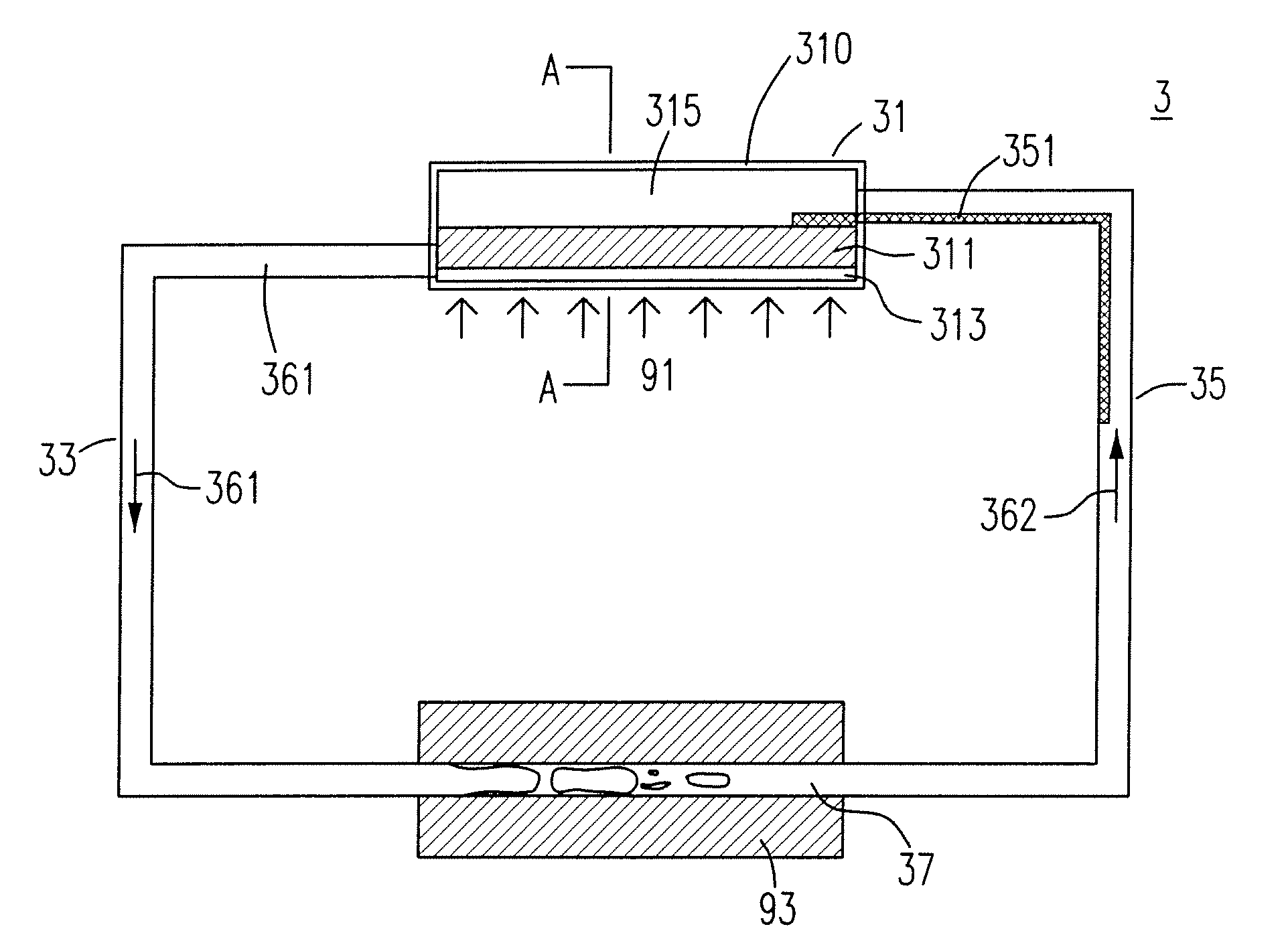
[0045]Please refer to FIG. 3(A) and FIG. 3(B), which are the structural diagrams showing a heat dissipation system in accordance with the first preferred embodiment of the present invention. In FIG. 3(A) and FIG. 3(B), a heat dissipation system 3 includes an evaporator 31, a vapor line 33, a liquid line 35 and a condenser 37, wherein the evaporator 31 is a plate chamber 310 configured by the upper lid and the lower lid. In general, the plate chamber 310 is made of the metal alloy with good thermal conductivity, for approaching or connecting to an external heat source 91 and sustaining the heat of the external heat source 91. The ...


PUM


Abstract

A heat dissipation system is provided. The heat dissipation system includes: an evaporator having a plate chamber with the wick structures which has a plurality of pore sizes arranged in the plate chamber, a condenser, a vapor line, and a liquid line. The two-phase circulation of the vapor-condensate in the heat dissipation system, especially in the heat dissipation system with a plate evaporator, can effectively increase the heat conductivity of the plate heat source such as electronic chip. The design and composition of the wick structures are enormously decreased the turning-on temperature of the heat dissipation system and maintained the heat dissipation system in the balancing state under the low heat source power.

Description

FIELD OF THE INVENTION[0001]The present invention relates to a heat dissipation system. In particular, the present invention relates to a heat pipe dissipation system with a plate evaporator.BACKGROUND OF THE INVENTION[0002]Thermal management is an issue which is essential in all kinds of categories, such as permafrost stabilization, electronic equipment cooling, and aerospace, etc. Heat pipe is a common application means in plenty of thermal management methods. Heat pipe is a two-phase heat conduction device, which can conduct heat with high efficiency and effectively.[0003]Please refer to FIG. 1, which is a structural diagram showing a traditional heat pipe device in accordance with the prior art. In FIG. 1, the heat pipe 1 is mainly configured by the tube 11, the wick structure 12 and the end caps 13. The interior of the heat pipe 1 is maintained in a low-pressured situation, and the adequate amount of the low-boiling point liquid 181 is injected in the interior thereof. The liqu...

Claims


Application Information

Patent Timeline
Patent Type & Authority Applications(United States)
IPC IPC(8): F28D15/04
CPCF28D15/043
Inventor CHANG, YEN-MINGCHIEN, KUO-HSIANG
Owner IND TECH RES INST
Why Eureka
Try Eureka