Device for Use with Liquid Container for a Vehicle and Method for Mounting Said Liquid Container

a technology for liquid containers and vehicles, which is applied in the direction of suspension devices, loading-carrying vehicle superstructures, transportation items, etc., can solve the problems of generating stress on the tank fittings, reducing the storage capacity of liquid containers, so as to maximize the available volume for liquid storage and maximize the utilization of available space. , the effect of reducing the size of the liquid container

Inactive Publication Date: 2008-11-20
VOLVO LASTVAGNAR AB
View PDF12 Cites 15 Cited by
  • Summary
  • Abstract
  • Description
  • Claims
  • Application Information

AI Technical Summary

Benefits of technology

[0007]The present invention aims to provide an improved fastening arrangement for a liquid tank for a vehicle, which fastening arrangement will simplify mounting and fixing of the tank to a bracket on the vehicle. The invention further aims to provide a tank that allows the available volume for the storage of liquid to be maximized.
[0008]It is desirable to provide a fastening arrangement for use with a liquid tank, which arrangement allows for maximum utilization of the available space for the storage of liquid. It is also desirable to provide a fastening arrangement that allows the liquid tank to be easily mounted and subsequently held securely fixed in a predetermined position. The tank is preferably, but not necessarily, intended for some form of propellant for the vehicle engine or an auxiliary engine, urea for the after-treatment of exhaust gases, water or other liquids.

Problems solved by technology

Circular tanks have the drawback that they offer a smaller liquid capacity.
They may also mm the risk of rotating relative to the fastening arrangement, thereby generating stresses upon the tank fittings, such as connecting elements for connecting pipes to the tank.
In this type of supporting bracket, the part reaching in beneath the tank requires space in the vertical direction, which means that the total space for tank and bracket cannot be utilized effectively for the storage of liquid, since the ground clearance requirement limits the space downward.
Owing to its extent transversely to the longitudinal axis of the vehicle, the tank must, however, be accurately positioned when mounted and must be clamped in place such that it cannot be turned or rotated in any direction, since a small turn in connection with the bracket can produce a relatively large displacement of the outer end of the tank.

Method used


Image

  • Device for Use with Liquid Container for a Vehicle and Method for Mounting Said Liquid Container
  • Device for Use with Liquid Container for a Vehicle and Method for Mounting Said Liquid Container
  • Device for Use with Liquid Container for a Vehicle and Method for Mounting Said Liquid Container

Examples


Embodiment Construction

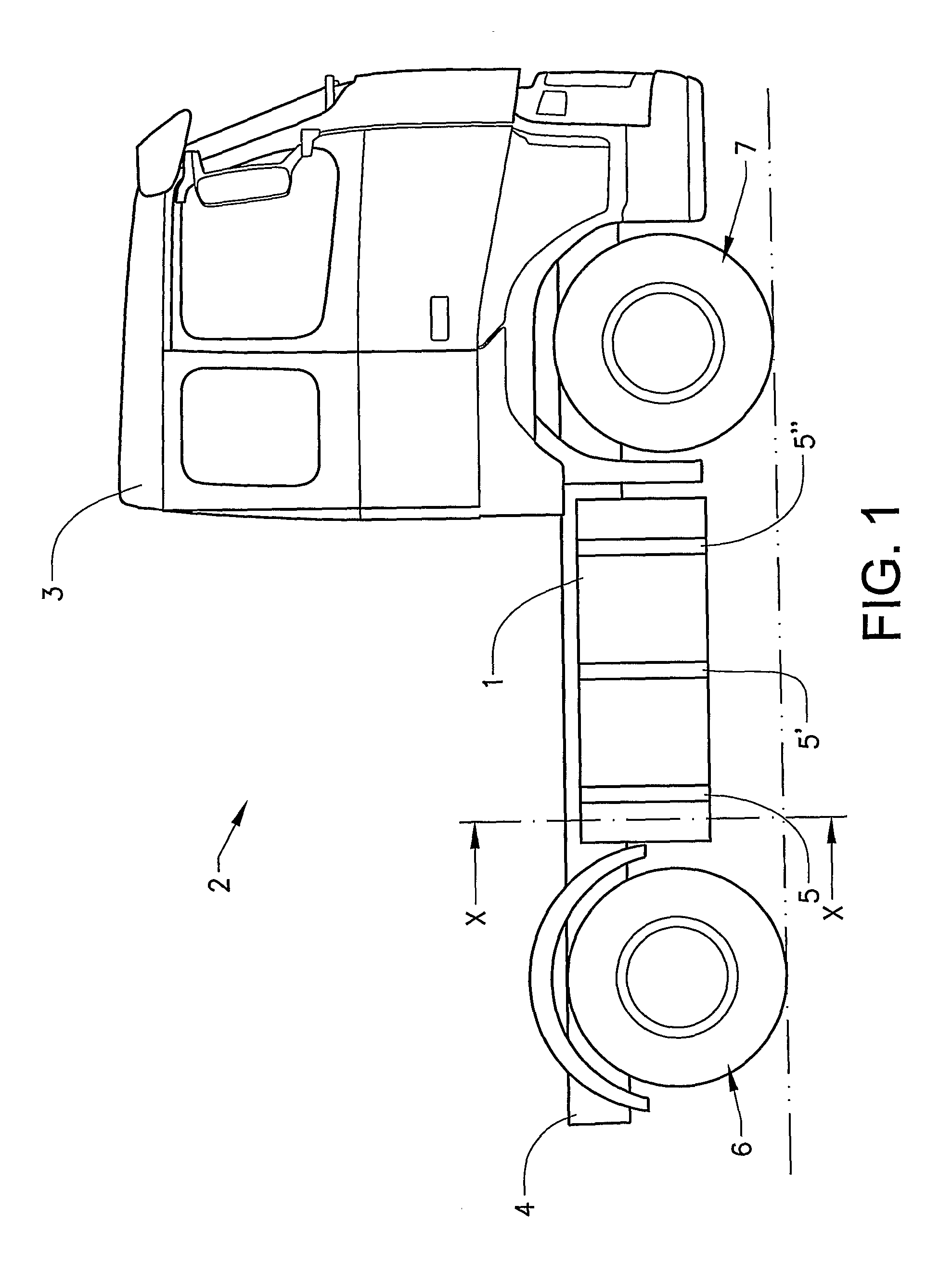
[0041]FIG. 1 shows a tank 1 according to the invention mounted on a vehicle 2. Although the vehicle shown is of the cab-forward type, having a drivers cab 3 located over an engine (not shown), the tank configuration is not limited to vehicles of this type. The tank 1 is mounted to a frame 4, including a pair of longitudinal U-shaped beams, by means of an attachment means comprising of three flexible straps 5, 5′, 5″ attached to a pair of supporting brackets bolted onto an outer substantially vertical surface on one or both sides of the vehicle. The arrangement of the straps will be described in further detail in connection with FIG. 3 below. In this embodiment, the tank 1 is located between a rear and a front wheel 6, 7 on the vehicle.

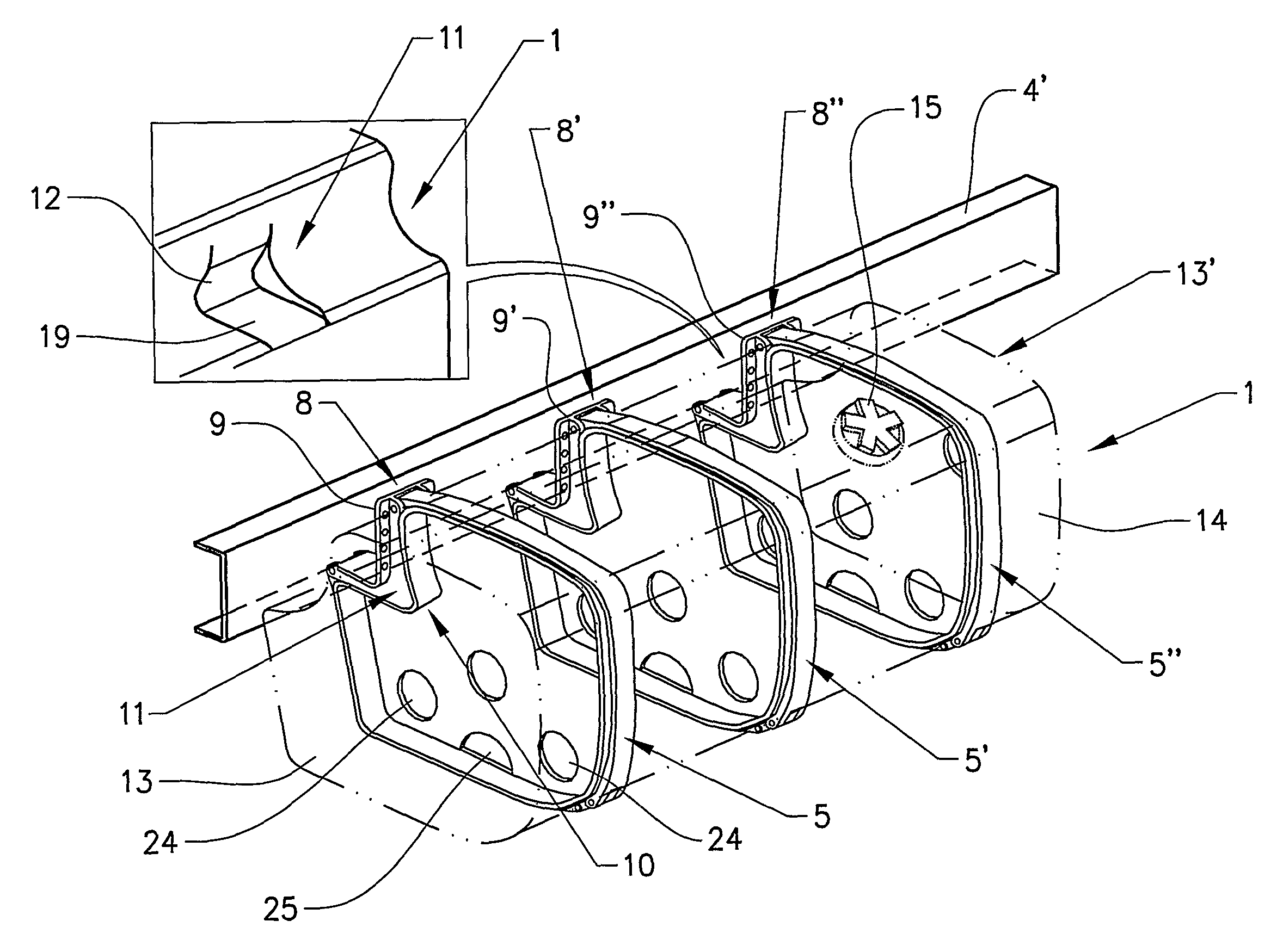
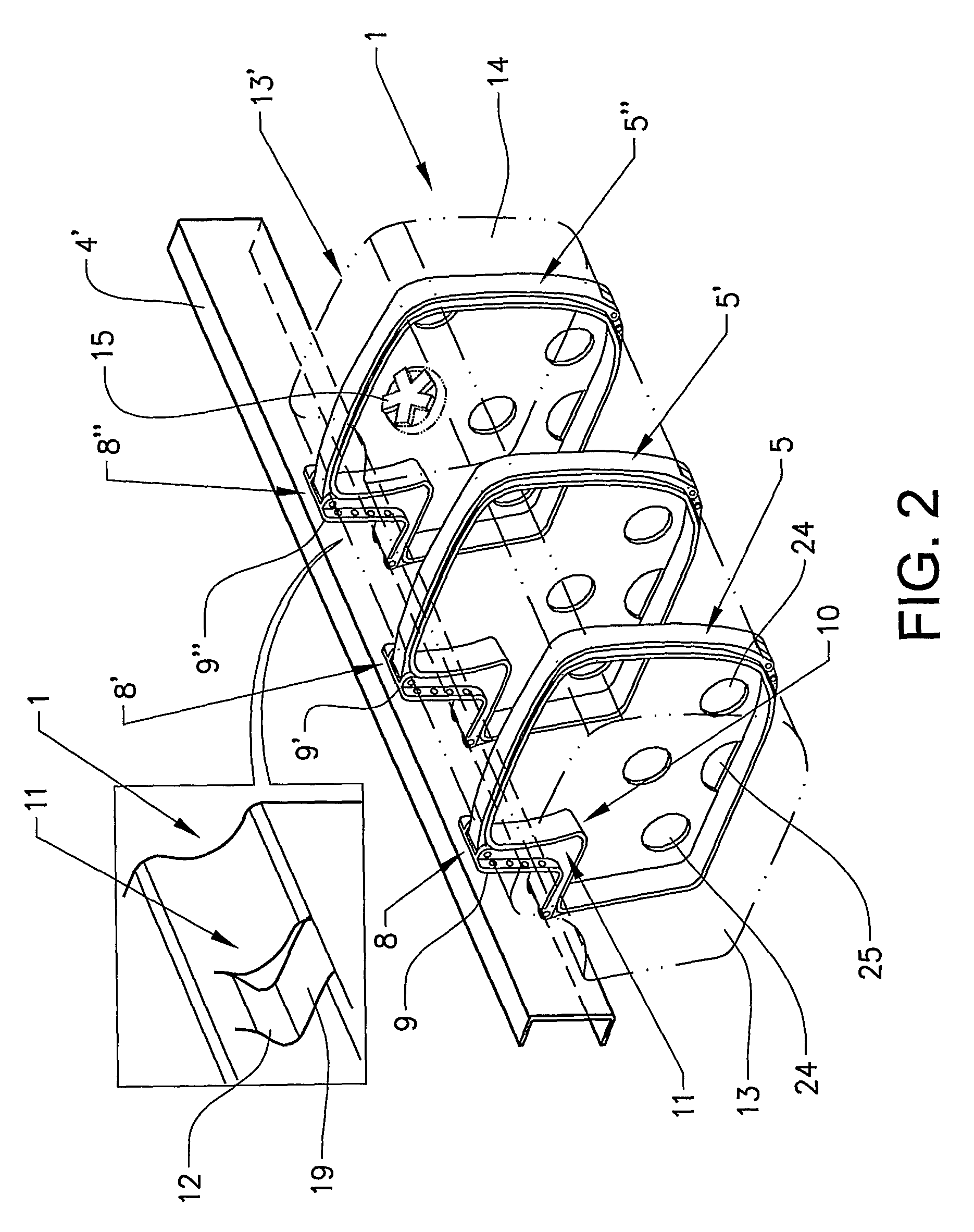
[0042]FIG. 2 shows a perspective view of one possible tank configuration according to a first embodiment of the invention. The tank 1, indicated by dashed lines for clarity, is fastened to a part of the vehicle frame 4 (see FIG. 1) in the form of a lon...


PUM


Abstract

A liquid tank is provided for a heavy vehicle, suitable for fastening to a vehicle frame by at least one supporting bracket having shaped surfaces arranged for load bearing and locating contact against the liquid tank. The tank includes two end face portions and a shell portion with a non-symmetrical cross-section extending there between. The tank includes a first, shaped portion facing the vehicle frame, arranged for load bearing contact against a first shaped surface of the supporting bracket, a second, shaped portion extending partially below the frame, arranged to locate the tank relative to a second shaped surface of the supporting bracket, and a third, substantially rectangular portion facing away from the vehicle frame, and that the tank is fastened to the bracket by at least one clamping means. A bracket for supporting such a tank is also disclosed.

Description

BACKGROUND AND SUMMARY[0001]The present invention relates to a device for use with a liquid tank for a vehicle, in particular a device for supporting and securing the liquid tank on the vehicle in the form of at least one supporting bracket fixed to the vehicle and provided with members for locating and securing the tank to the supporting bracket, and to a tank having locating members for facilitating mounting and fixing of the tank to the supporting bracket.[0002]Liquid tanks for heavy vehicles, especially fuel tanks and the like for heavy goods vehicles, are usually configured in substantially cylindrical form with two end faces and an intermediate shell surface. There are two main types of tanks available on the market, one of which has circular-cylindrical cross-section, hereinafter referred to as a circular tank, and the other of which has a rectangular-cylindrical, hereinafter referred to as a rectangular tank. In addition, an alternative type of tank forms a combination of th...

Claims


Application Information

Patent Timeline
Patent Type & Authority Applications(United States)
IPC IPC(8): B60K15/067
CPCB60K15/067B60Y2200/14
Inventor LEVIN, GORANBODIN, JAN-OLOF
Owner VOLVO LASTVAGNAR AB
Why Eureka
Try Eureka