Doppler radar systems

Active Publication Date: 2008-11-20
BLIGHTER SURVEILLANCE SYST LTD
View PDF8 Cites 28 Cited by
  • Summary
  • Abstract
  • Description
  • Claims
  • Application Information

AI Technical Summary

Benefits of technology

[0013]Preferably the constant rate is selectable in dependence on said duration of individual modulation patterns of the sequence and each cycle of audio data comprises data derived from one or more said modulation patterns in the sequence. The data derived from one said modulation pattern in the sequence is played back at least once in each cycle of audio data, and, in the case where the audio rate is greater than that correspondin

Problems solved by technology

A particular problem encountered when employing frequency scanning antennas is that the inherent and required variation in frequencies will modify the Doppler frequencies for a given target, thus modifying the in

Method used


Image

  • Doppler radar systems
  • Doppler radar systems
  • Doppler radar systems

Examples


Embodiment Construction

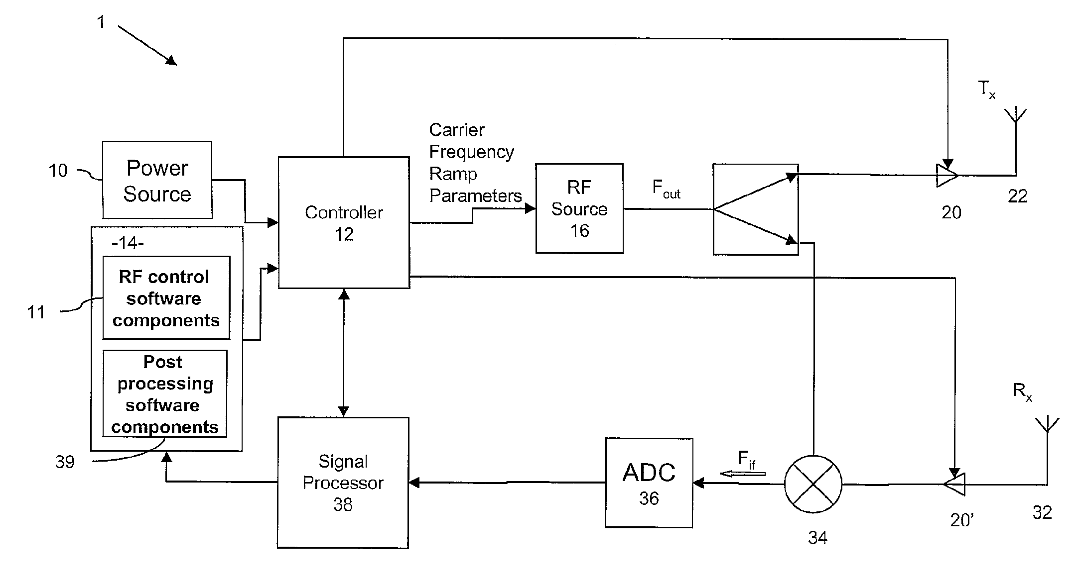
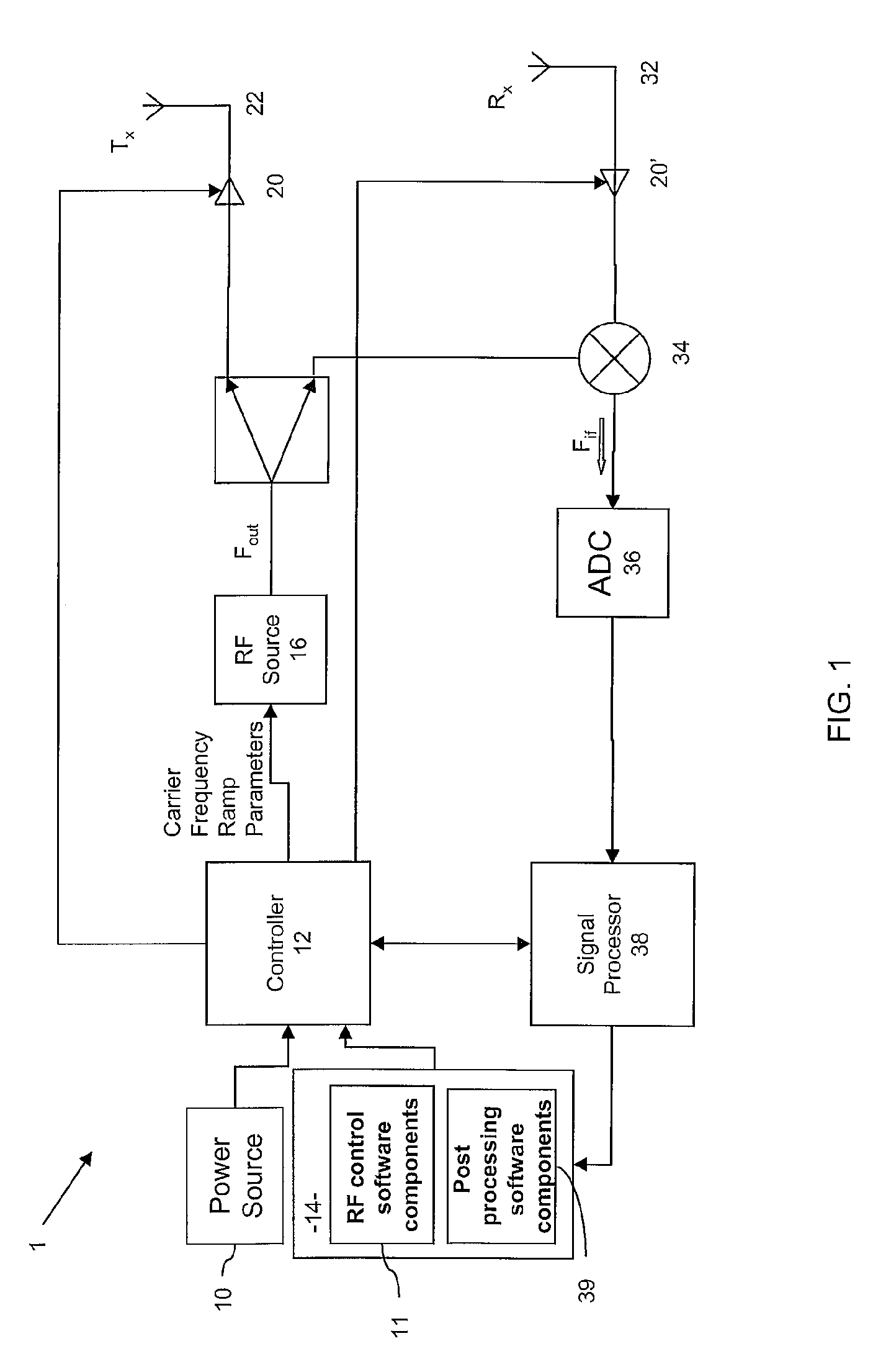
[0023]FIG. 1 shows a radar system 1 with which embodiments of the invention operate, the radar system 1 comprising a power source 10, a controller 12, and a computer 14, the power source and computer 10, 14 being arranged to provide power to, and operational control over, the controller 12. The controller 12 comprises a microprocessor and a set of instructions (not shown) for execution thereby, effectively generating control signals that cause the RF frequency source, or signal generator 16, to output RF energy at a specified frequency FOUT, and this output signal, under control of amplifiers 20, drives antenna 22. As will be described in more detail below, the RF frequency source 16 generates signals within a range of frequencies, causing the antenna 22 to transmit beams in different angular directions, thereby scanning over a region beyond the radar system 1.

[0024]The radar system 1 also includes a receiving antenna 32, which receives radiated signals reflected back from objects, ...


PUM


Abstract

Embodiments of the invention are concerned with improvements to Doppler radar systems, and are suitable for use with frequency scanning radar systems.
In one arrangement the improvements are embodied in a frequency scanning radar controller for use in controlling a frequency generator; the frequency generator is arranged to generate a plurality of sets of signals, each set of signals having a different characteristic frequency and comprising a plurality of signals transmitted at a selected rate, and the radar controller is arranged to select the rate in dependence on the characteristic frequency.
The invention can be embodied in a pulsed radar, for which each set of signals comprises a set of pulsed signals and each pulsed signal is repeated at a selected repetition rate. The radar controller is then arranged to modify the repetition rate in dependence on the characteristic frequency of the pulsed signal. The invention can alternatively be embodied in a frequency modulated radar system, for which each set of signals comprises a sequence of modulation patterns. The radar controller is then arranged to modify a given modulation pattern in dependence on the characteristic frequency of the signal being modulated.

Description

CROSS REFERENCE TO RELATED APPLICATIONS[0001]This application claims the benefit of International Patent Application No. PCT / EP2006 / 068731 filed on Nov. 21, 2006 and entitled “IMPROVEMENTS TO DOPPLER RADAR SYSTEMS”, the contents and teachings of which are hereby incorporated by reference in their entirety.FIELD OF THE INVENTION[0002]The present invention relates to improvements to Doppler radar systems, and is particularly, but not exclusively, suitable for use with frequency scanning radar systems.BACKGROUND OF THE INVENTION[0003]Radar systems are used to detect the presence of objects and to measure the location and movement of objects. It is common for such radar systems to sweep across a given region, scanning the region for the presence of such objects. In order to sweep over the region the radar systems either employ mechanical devices comprising an antenna that physically moves in space, or electronic devices comprising elements that are arranged to steer radiation as it is t...

Claims


Application Information

Patent Timeline
IPC IPC(8): G01S13/00
CPCG01S7/4008G01S13/227G01S13/24H01Q25/00G01S13/426H01Q3/22G01S13/343G01S13/42
Inventor SPREADBURY, DAVID
Owner BLIGHTER SURVEILLANCE SYST LTD
Why Eureka
Try Eureka