Antenna Configuration for RFID Tags

a technology of antenna configuration and rfid tag, which is applied in the direction of rhombic antennas, non-resonant long antennas, instruments, etc., can solve the problems of reducing efficiency, unusable restrictions, and the antenna configuration known from the abovementioned patent document cannot be used, so as to improve the antenna configuration

Inactive Publication Date: 2008-11-20
NXP BV
View PDF10 Cites 4 Cited by
  • Summary
  • Abstract
  • Description
  • Claims
  • Application Information

AI Technical Summary

Benefits of technology

[0006]It is an object of the invention to avoid the abovemention

Problems solved by technology

However, such a great overall length results in undesirable restrictions since a product in which the known antenna configuration is used must have an overall length, which is greater than the overall length of the antenna configuration.
In such cases, the antenna configuration known from the abovementioned patent document cannot be used since this known antenna configuration has too great an overall length.
Although this means

Method used


Image

  • Antenna Configuration for RFID Tags
  • Antenna Configuration for RFID Tags
  • Antenna Configuration for RFID Tags

Examples


Embodiment Construction

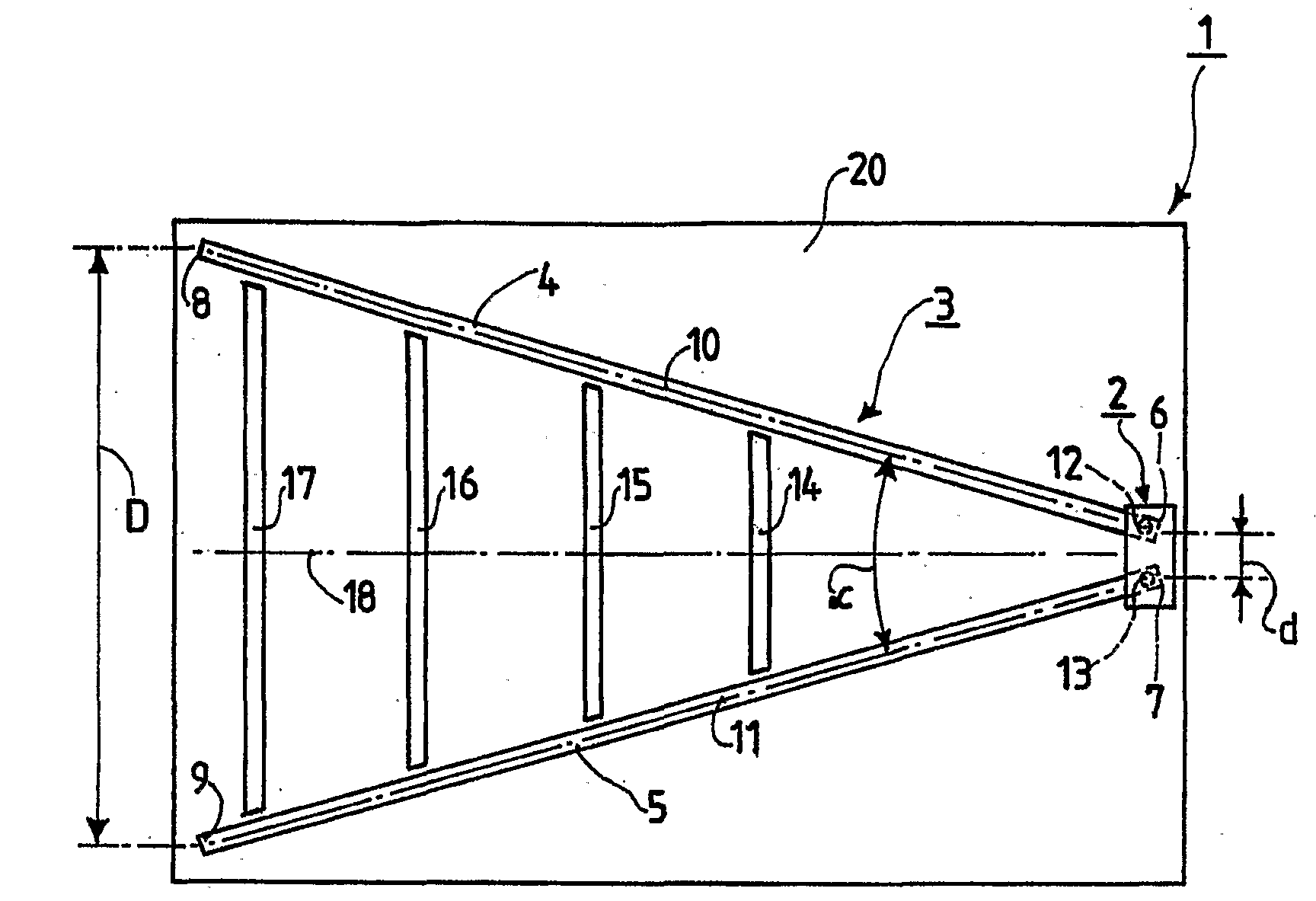
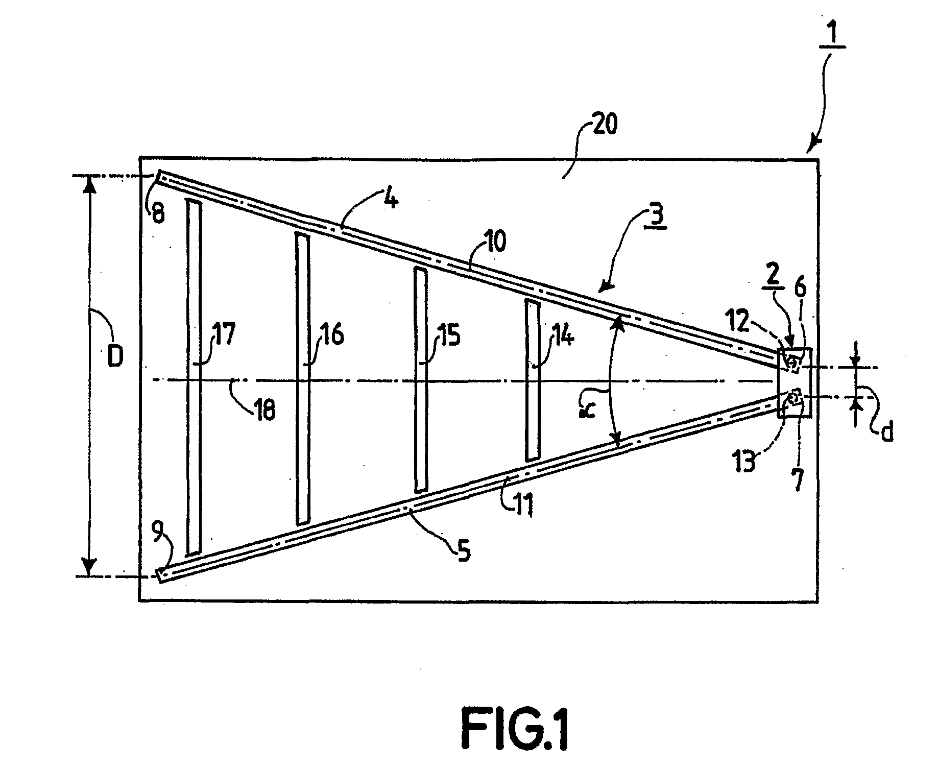
[0029]FIG. 1 shows a data carrier, which in this case is a label, usually referred to as a tag. The tag 1 shown in FIG. 1 has a substrate 20, which in the present case is made of a film-like plastic material with electrically insulating properties. The substrate 20 may however also be made of paper or board or a base material for a printed circuit board. The tag 1 furthermore has an IC 2 and an antenna configuration 3, which is connected to the IC 2 in an electrically conductive manner.

[0030]The IC 2 is designed as a so-called transponder IC which has a data memory and data processing means which cooperate with said data memory, the transponder IC being provided to receive and transmit data, which data identify specific articles, goods and other products. The antenna configuration 3 is provided in order to be able to transmit the abovementioned data to the IC 2 and from the IC 2 in a contactless manner, which antenna configuration 3 is designed for contactless cooperation with a sta...


PUM


Abstract

In an antenna configuration (3) having a first antenna arm (4) and having a second antenna arm (5), the two longitudinal directions (10, 11) of the two antenna arms (4, 5) enclose an acute opening angle (α) with one another, wherein the acute opening angle (α) has a value of between 15° and 90° and preferably between 25° and 45°.

Description

FIELD OF THE INVENTION[0001]The invention relates to an antenna configuration which has a first antenna arm and a second antenna arm, wherein each of the two antenna arms is made of electrically conductive material and has a first end and a second end and has a longitudinal direction which runs from the first end to the second end, and wherein the two first ends are arranged at a first distance from one another and adjacent to one another and are in each case intended and designed for electrically conductive connection to a terminal of a signal sink or of a signal source, and wherein the two second ends are arranged at a second distance from one another and remote from one another, said second distance being greater than the first distance.[0002]The invention furthermore relates to a data carrier for contactless communication with a communication station, which data carrier is provided with an antenna configuration for contactless communication.BACKGROUND OF THE INVENTION[0003]Such ...

Claims


Application Information

Patent Timeline
IPC IPC(8): H01Q11/06G06K19/077H01Q1/38H01Q9/44
CPCG06K19/07749
Inventor HILGERS, ACHIM
Owner NXP BV
Why Eureka
Try Eureka