Differentially-fed variable directivity slot antenna
- Summary
- Abstract
- Description
- Claims
- Application Information
AI Technical Summary
Benefits of technology
Problems solved by technology
Method used
Image

Examples
embodiment
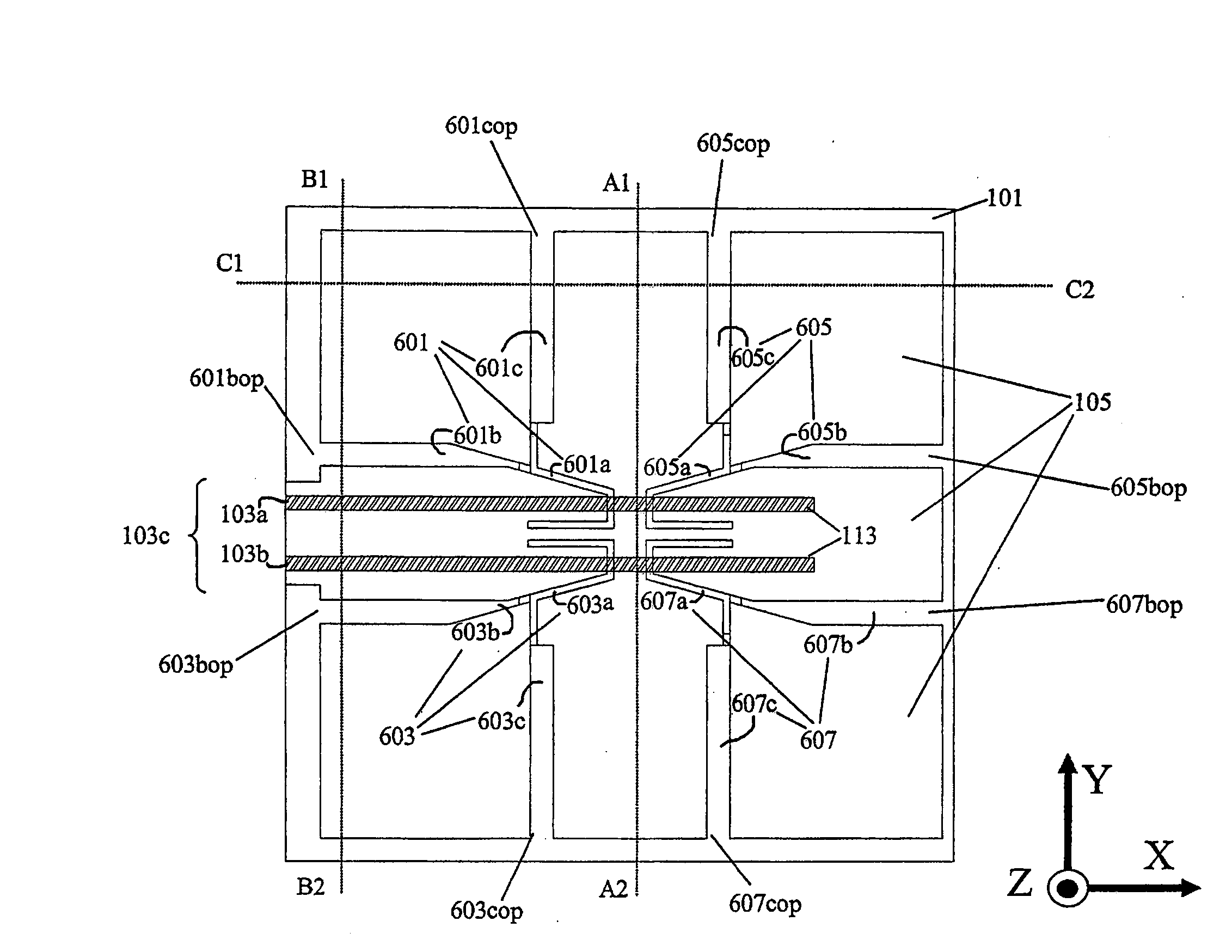
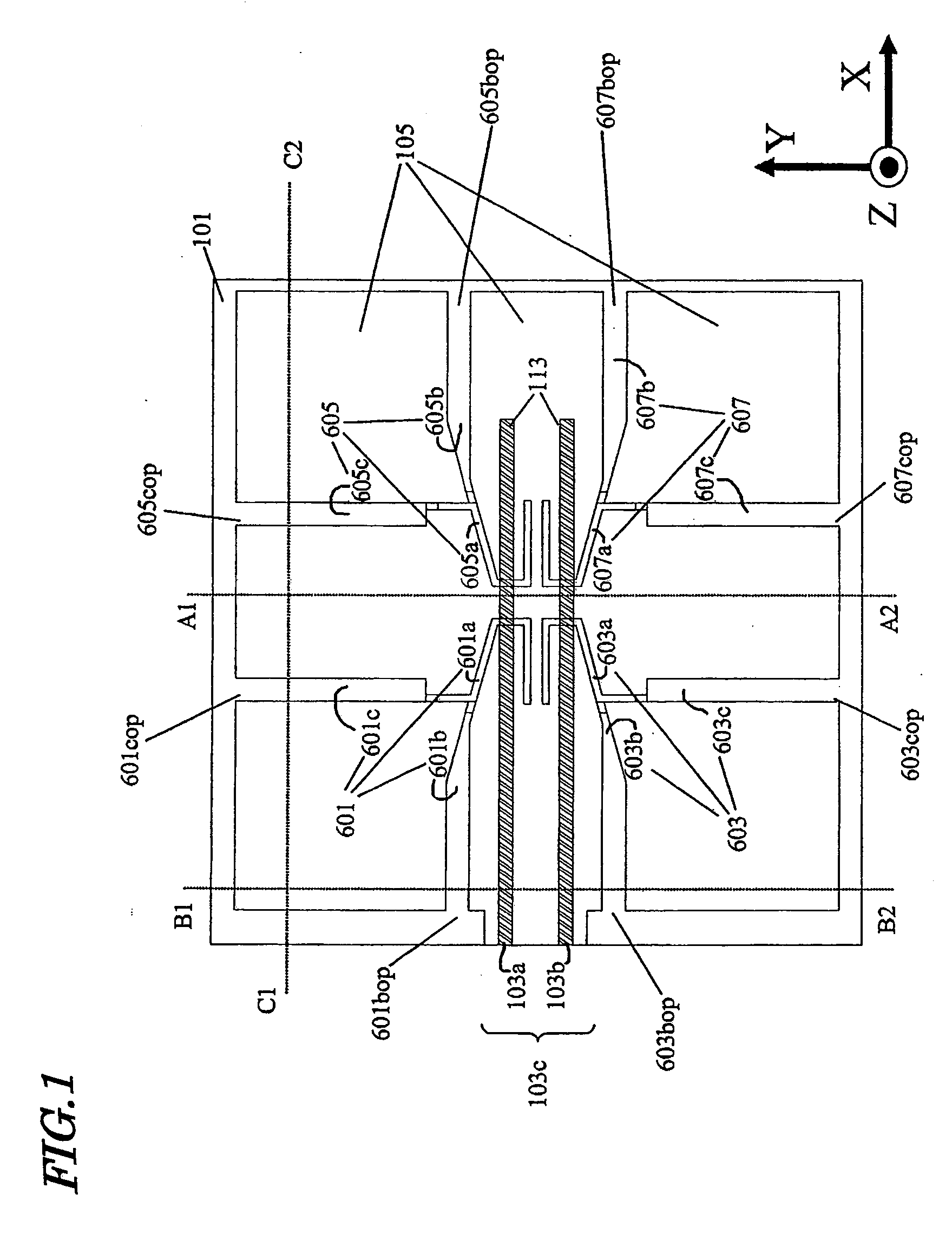
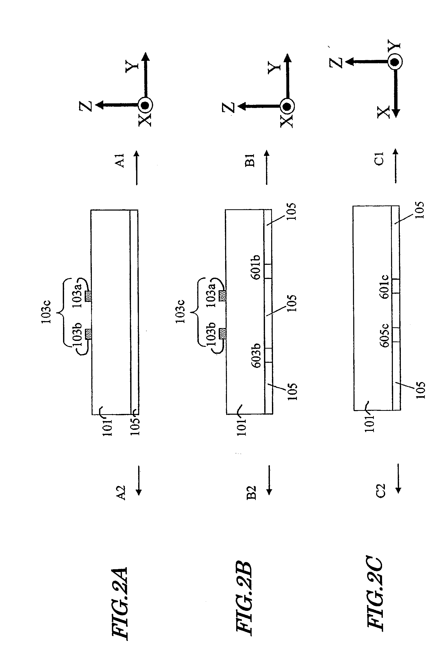
[0060]FIG. 1 shows the structure of an embodiment of the differentially-fed slot antenna according to the present invention, and provides a schematic see-through view as seen through a ground conductor on the rear face of a dielectric substrate. FIGS. 2A to 2C are cross-sectional structural diagrams of the circuit structure taken along line A1-A2, line B1-B2, and line C1-C2 in FIG. 1, respectively. The coordinate axes and signs in the figures correspond to the coordinate axes and signs in FIGS. 17A and 17B and FIGS. 22A to 22C showing constructions and radiation directions of Conventional Examples.
[0061]As shown in FIG. 1, a ground conductor 105 having a finite area is formed on the rear face of a dielectric substrate 101, and a differential feed line 103c is formed on the front face of the dielectric substrate 101. The differential feed line 103c is composed of a mirror symmetrical pair of signal conductors 103a and 103b. In partial regions of the ground conductor 105, the conducto...
examples
[0091]On an FR4 substrate measuring 30 mm along the X axis direction, 32 mm along the Y axis direction, and 1 mm along the Z axis direction, a differentially-fed variable directivity slot antenna according to the present invention as shown in FIG. 1 was fabricated. On the substrate surface, a differential feed line 103c having a line width of 1.3 mm and a line-to-line gap of 1 mm was formed. From a ground conductor 105 formed on the entire substrate rear face, the conductor was removed in partial regions by wet etching, thus realizing a slot structure. The conductor was a piece of copper having a thickness of 35 microns. The four slot resonators were all made identical in shape. The slot resonator 601 and the slot resonator 603 were placed so as to be mirror symmetrical; and so were the slot resonator 605 and the slot resonator 607. Furthermore, the slot resonator 601 and the slot resonator 605 were placed so as to be mirror symmetrical; and so were the slot resonator 603 and the sl...
first example
[0095]In the First Example, the high-frequency switches of each slot resonator were controlled so as to realize the first control state shown in FIG. 6. A radiation pattern on each coordinate plane in this Example is shown in FIG. 12. As is clear from FIG. 12, it was proven that the first control state realizes a main beam direction being oriented in the ±Y direction. In the Z axis direction, a gain suppression effect exceeding 25 dB was obtained relative to the gain in the main beam direction. In the X axis direction, too, a gain suppression effect of almost 20 dB was obtained relative to the gain in the main beam direction.
PUM
 Abstract
Description
Claims
Application Information
 - R&D Engineer
- R&D Manager
- IP Professional
- Industry Leading Data Capabilities
- Powerful AI technology
- Patent DNA Extraction
Browse by: Latest US Patents, China's latest patents, Technical Efficacy Thesaurus, Application Domain, Technology Topic.
© 2024 PatSnap. All rights reserved.Legal|Privacy policy|Modern Slavery Act Transparency Statement|Sitemap