
System and method for registration of cubic fisheye hemispherical images

a technology of hemispherical images and system and methods, applied in image data processing, instruments, surveying and navigation, etc., can solve the problems of inconvenient use, inconvenient use, and inability to accurately capture images in the same area on the recording surfa

Inactive Publication Date: 2008-11-20
ILOOKABOUT
View PDF45 Cites 11 Cited by
  • Summary
  • Abstract
  • Description
  • Claims
  • Application Information

AI Technical Summary

Benefits of technology

"This patent describes a system and method for combining images from a fisheye lens to create a panoramic view. The system uses a single translation and rotation model to determine the displacement of the images and evaluates the center of projection, distance in pixels, and the extent of translation and rotation. The method also iterates to color balance the images by adjusting the values of pixels near the edge of the image based on the average difference of pixel color across the edge of a strip of decreasing width. This invention removes color differences without affecting the details of the image."

Problems solved by technology

It has been speculated that a field of view infinitesimally less than 360 degrees is also obtainable, although the precise practical application of a lens of this type may be limited.
Producing high-quality panoramic imaging using Greene's approach poses a number of difficulties.
Registration of the half-images has two associated problems: spatial alignment and colour balancing.
Furthermore, the image recording device would not necessarily capture the images precisely in the same area on the recording surface.
This is often imprecise and difficult due to the multiple sources of distortion.
If aperture size is controlled automatically, further mismatches may result.
However, the disadvantage concerns the concomitant loss of detail.
When the width of the overlapped region is narrow as compared to lighting imbalance, the transition may appear too abrupt.

Method used


Image

  • System and method for registration of cubic fisheye hemispherical images
  • System and method for registration of cubic fisheye hemispherical images
  • System and method for registration of cubic fisheye hemispherical images

Examples


Embodiment Construction

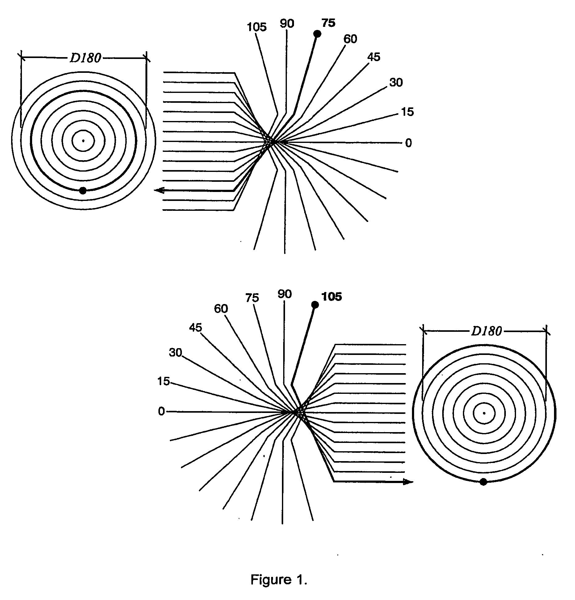
[0019]The description given below assumes the use of an ideal fisheye lens, meaning that the lens possesses negligible if no radial distortion: the radial position recorded in the source image for a point imaged is proportional to the zenith angle the point subtends with respect to the axis of projection (see FIG. 1). However, a person knowledgeable in the art would be able to extend the invention disclosed below to the case where there is radial distortion. Adjustment to take into consideration lens characteristics are clear once the characteristics are determined.

[0020]Furthermore, the fisheye lens has a field of view greater than 180 degrees.

Overview

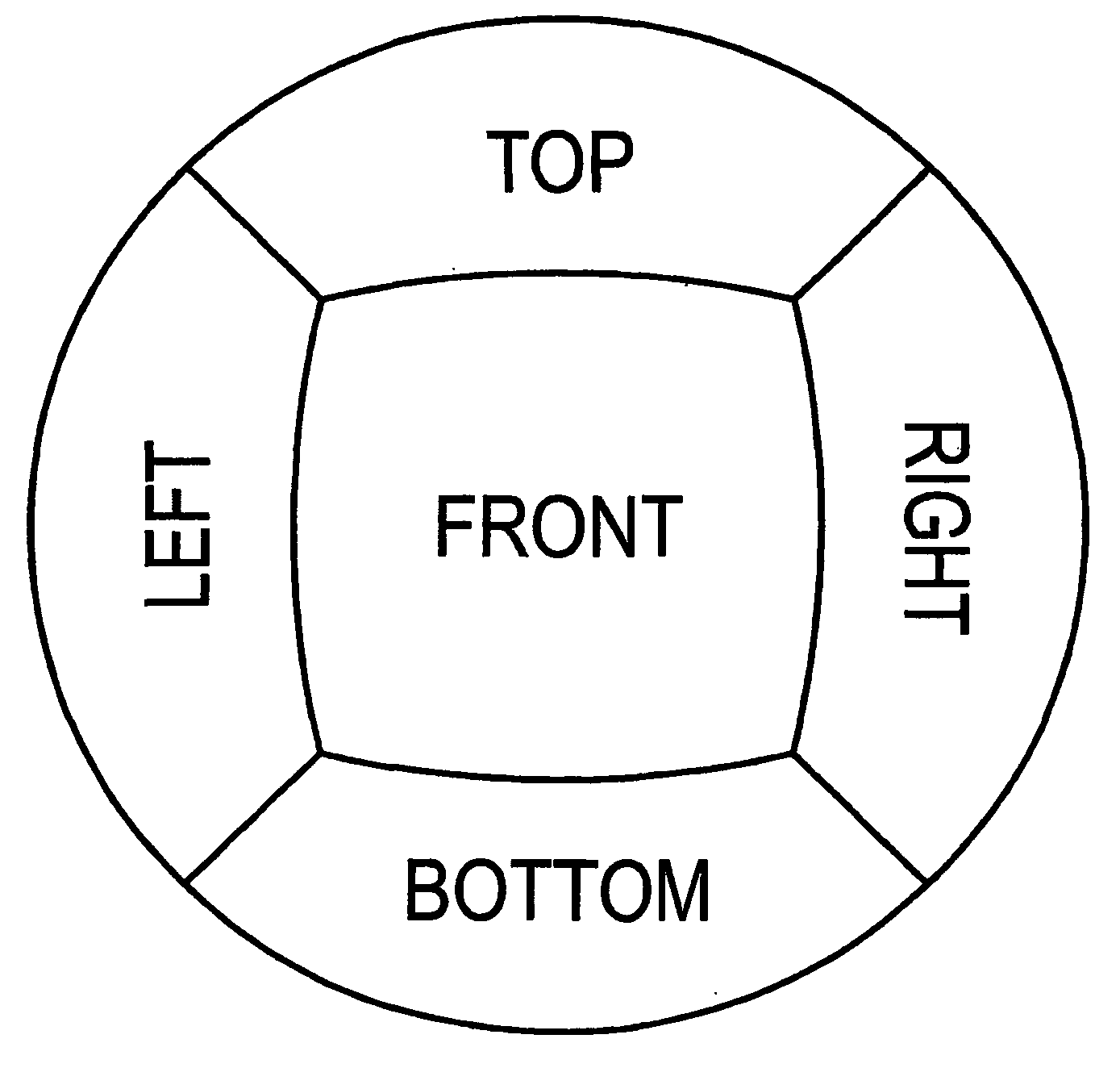
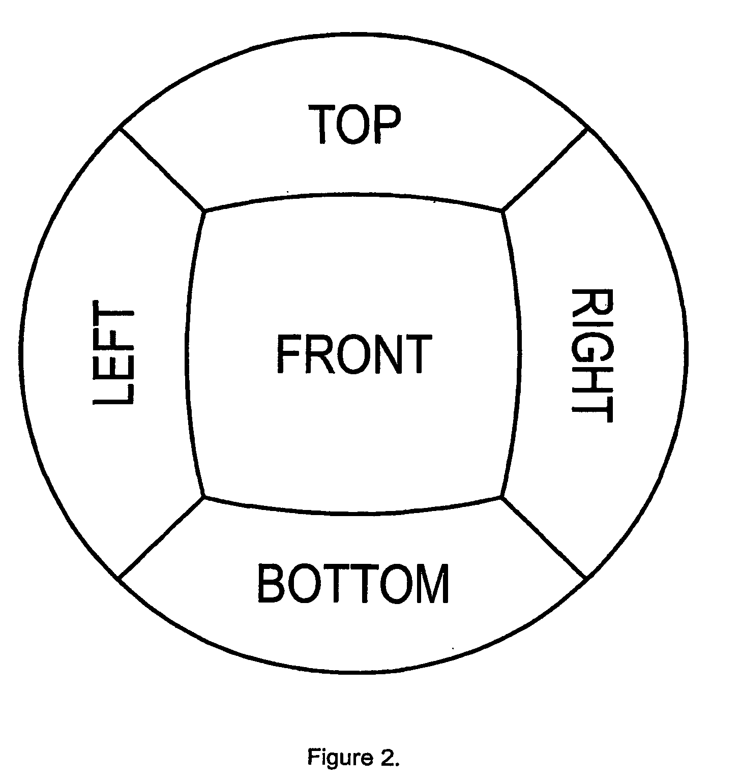
[0021]In the present invention, an environmental map of cube consisting of 6 canonical views is reconstructed from two hemispherical fisheye images, as Greene had suggested, each with field of view equal or greater than 180 degrees. Each fisheye image is manipulated to generate 1 complete side and 4 half-sides of a cube; and the half ...


PUM


Abstract

Systems and methods for registering hemispheric images obtained using a fisheye lens for panoramic viewing, relating to spatial alignment and colour balancing of complement half-side images derived from the hemispheric images. The systems and methods for spatial alignment determine the displacement of the digitized recorded images using a single translation and rotation model of distortion, which further evaluates the centre of projection, and the extent of translation and rotation. The system and method for colour balancing iteratively increase (or decrease) the values of pixels near the edge (discontinuity) between the two half-sides of an image, each time taking into consideration the average difference of pixel colour across a smaller strip of the edge near the pixel. This invention removes the colour differential but does not remove any detail underlying the features of the image.

Description

CROSS-REFERENCE TO RELATED APPLICATIONS[0001]This application is a continuation of U.S. application Ser. No. 10 / 433,906, filed Dec. 7, 2001 as PCT / CA01 / 01755, which claims the benefit of U.S. Provisional Application No. 60 / 279,662, filed Mar. 30, 2001.FIELD OF THE INVENTION[0002]This invention relates to systems and methods for registering hemispheric images for panoramic viewing. In particular it relates to spatial alignment and colour balancing of images.BACKGROUND AND GENERAL DESCRIPTION[0003]Fisheye lens has experienced success in a number of applications involving panoramic or wide field-of-view applications. Such would include cinematography (U.S. Pat. No. 4,070,098), motionless surveillance (U.S. patent RE036207), and image-based virtual reality (U.S. Pat. No. 5,960,108).[0004]The advantage of fisheye projection is its large field of view compared to conventional rectilinear film. Images of field of view up to 220 degrees and beyond may be obtained with a fisheye lens. It has...

Claims


Application Information

Patent Timeline
Patent Type & Authority Applications(United States)
IPC IPC(8): G09G5/377G06T3/00
CPCG06T3/0018G06T3/12
Inventor HACK, JEFF
Owner ILOOKABOUT
Learn More