
Thermal assembly coupled with an appliance

a technology of an appliance and a thermal assembly, applied in the field of connecting features of an appliance and an appliance member, can solve problems such as problems that can be encountered, and achieve the effect of convenient mounting

Active Publication Date: 2008-11-20
GROUP DEKKO
View PDF54 Cites 8 Cited by
  • Summary
  • Abstract
  • Description
  • Claims
  • Application Information

AI Technical Summary

Benefits of technology

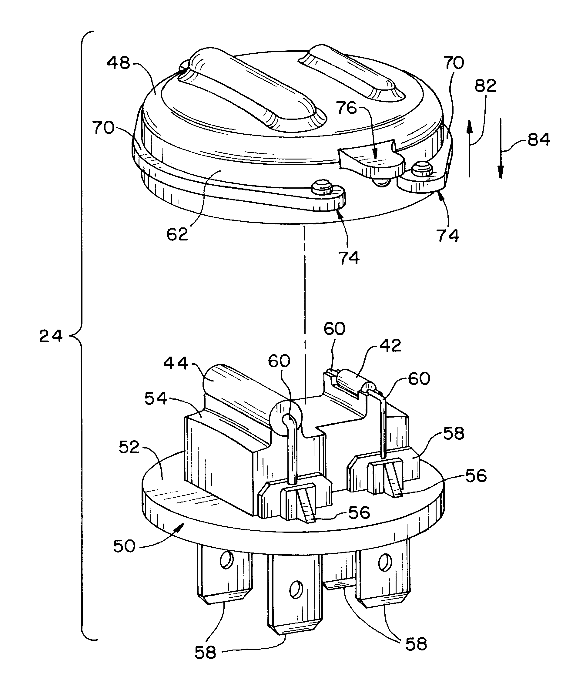
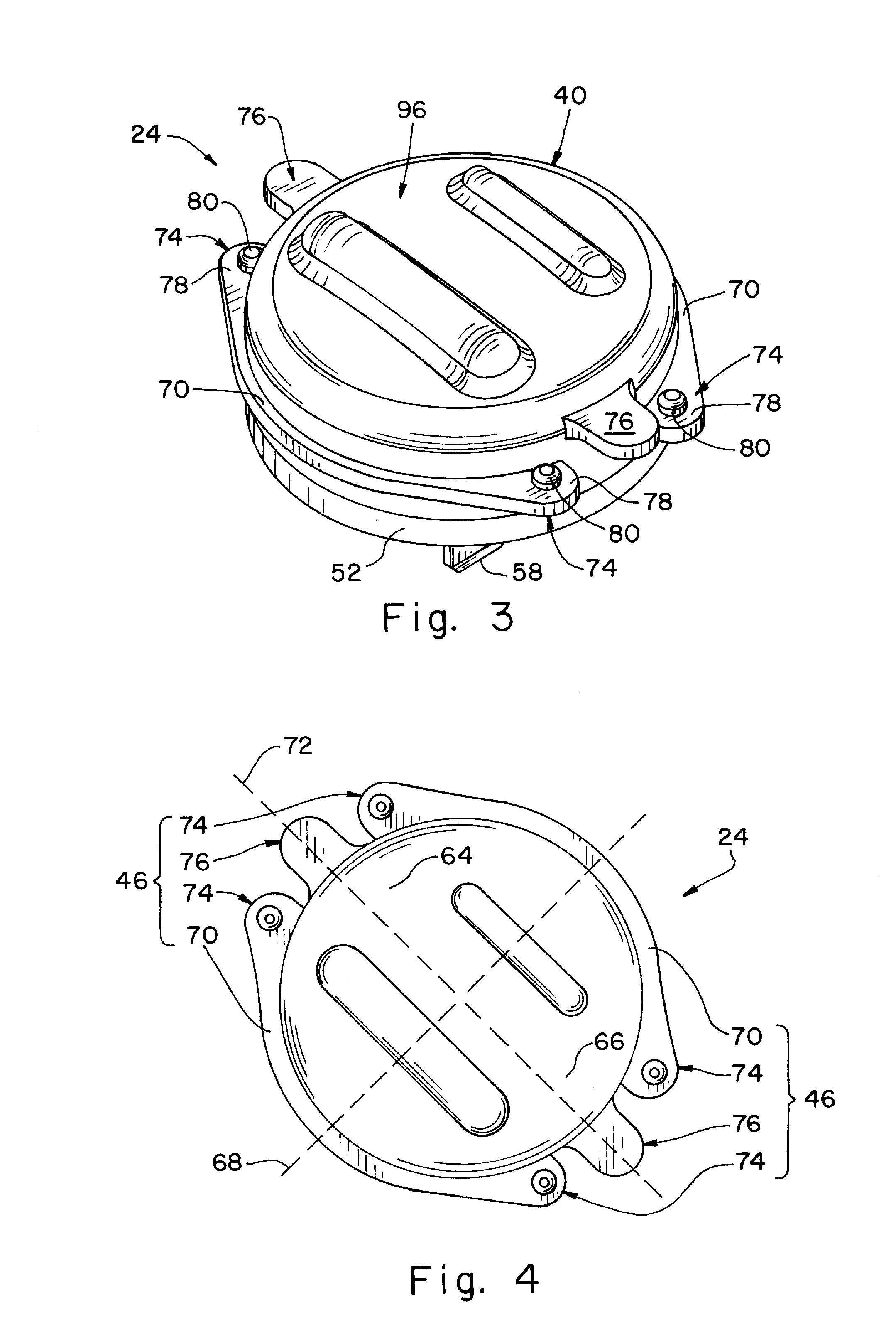
The present invention provides a simple and easy-to-use tool-less snap-fit arrangement for connecting an appliance member to an appliance. The snap-fit arrangement includes a housing with a plurality of ears that snap-fittingly engage with a plurality of holes defined by the appliance's wall. This allows for easy and quick mounting of the appliance member without the need for tools. The technical effects of the invention include improved efficiency and convenience in the mounting process.

Problems solved by technology

Difficulty, however, can be encountered when trying to mount the thermostat to the surface supporting portion of the dryer, particularly considering the bending or squeezing of one of the wing members, the pivoting of the thermostat into the central opening, and the pushing of a flat instrument such as a screwdriver downwardly between the squeezed wing and a bulb portion of the thermostat to force the arm of the squeezed wing to take on its final position.

Method used


Image

  • Thermal assembly coupled with an appliance
  • Thermal assembly coupled with an appliance
  • Thermal assembly coupled with an appliance

Examples


Embodiment Construction

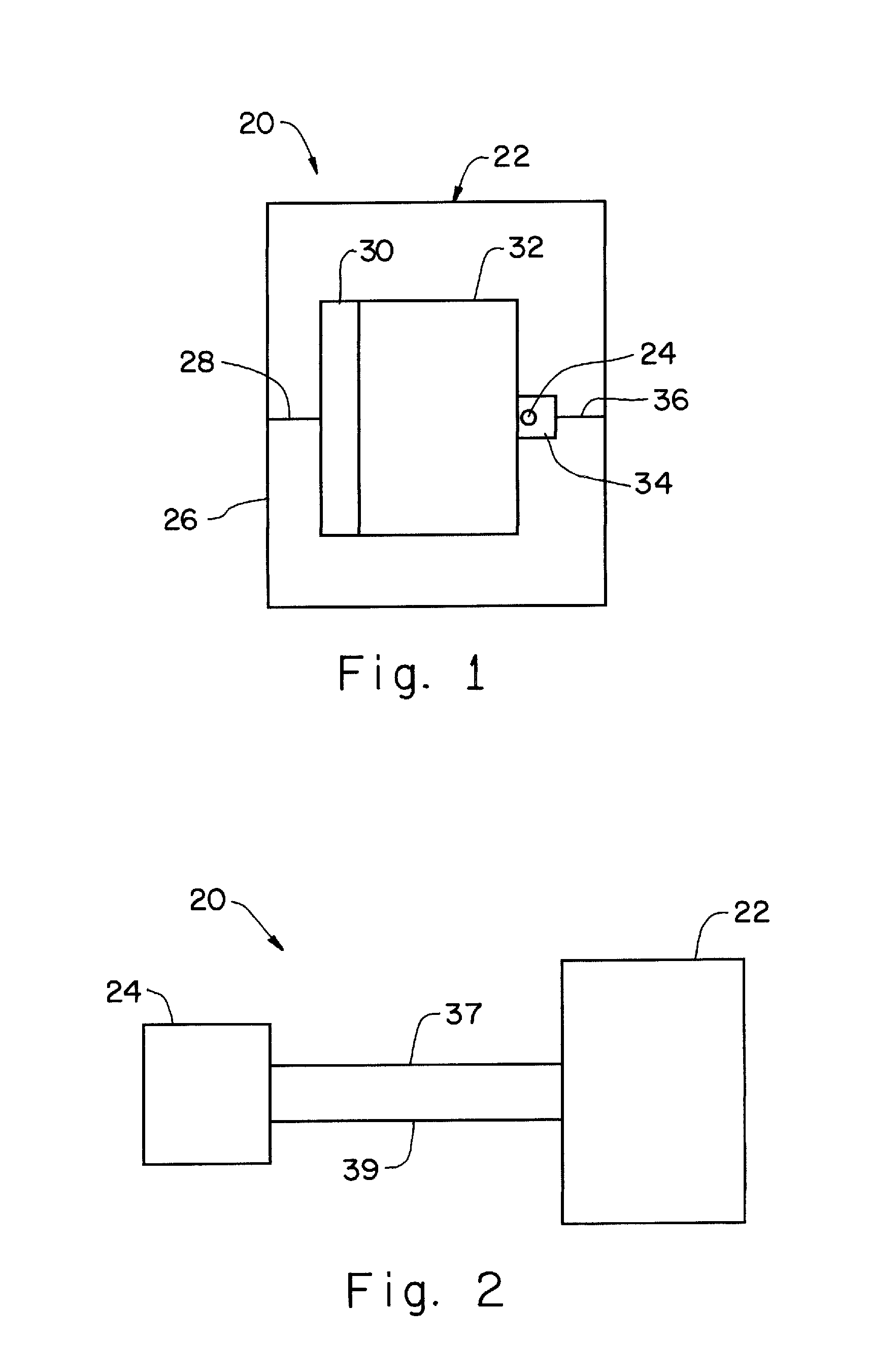
[0026]Referring now to the drawings, and more particularly to FIGS. 1-2, there is shown an appliance assembly 20 which generally includes an appliance 22 and an appliance member 24, which can be a thermal assembly 24. Appliance 22 can be, for example, a laundry dryer, a dishwasher, an oven, and / or any other appliance that produces heat using a heater or incidental heat. This listing of appliances is not intended to be limiting.

[0027]FIG. 1 shows that appliance 22 (a laundry dryer 22) includes an external housing 26, an air intake 28, a fan (not shown), a heater 30, a rotating drum 32, an exhaust gas outlet or housing 34 (for example, an exhaust gas outlet manifold 34 or, simply, a dryer manifold 34), a hot air exhaust line 36, and thermal assembly 24. In general, the fan can be used to draw ambient air into air intake 28. That ambient air can then be heated by heater 30 (which can be a heating coil), and thus heater 30 can be used to heat the interior of rotating drum 32 of the clot...


PUM


Abstract

An appliance assembly includes an appliance and an appliance member. The appliance includes a wall defining a plurality of holes. The appliance member is carried by the appliance. The appliance member includes a housing which includes a snap-fit arrangement coupled with the appliance. The snap-fit arrangement includes a first plurality of ears and a second plurality of ears, the first and second plurality of ears snap-fittingly engaging the plurality of holes.

Description

CROSS REFERENCE TO RELATED APPLICATIONS[0001]This is a non-provisional application based upon U.S. provisional patent application Ser. No. 60 / 938,319, entitled “THERMAL FUSE AND TEMPERATURE CONTROL DEVICE ASSEMBLY”, filed May 16, 2007, which is incorporated herein by reference.BACKGROUND OF THE INVENTION[0002]1. Field of the Invention[0003]The present invention relates to appliances, and, more particularly, to connecting features of an appliance and an appliance member.[0004]2. Description of the Related Art[0005]Appliances, such as a clothes dryer, which have a heater can have a temperature sensing device, such as a thermostat. A thermostat mounting arrangement can include such a thermostat mounted to a surface supporting portion of the clothes dryer to sense temperature conditions in the dryer. This mounting arrangement has an aperture passing through the surface support portion, the aperture having an enlarged central opening with four projection tab members extending into the ce...

Claims


Application Information

Patent Timeline
Patent Type & Authority Applications(United States)
IPC IPC(8): H05K7/00
CPCD06F58/26G01K13/00H01H37/74D06F34/26D06F2103/32D06F2103/52D06F2105/28
Inventor SCHEIBER, JOSEPH J.COVERSTONE, MICHAEL S.LEWIS, JEREMIAH
Owner GROUP DEKKO
Learn More