Delivery system having a self-expanding braided stent

Active Publication Date: 2008-11-20
JOTEC
View PDF12 Cites 34 Cited by
  • Summary
  • Abstract
  • Description
  • Claims
  • Application Information

AI Technical Summary

Benefits of technology

[0021]Against this background, an object of the present invention is to further develop the known delivery system in such a way that, by sim

Problems solved by technology

The inventors of the present application have in fact found that the problems of the known delivery syst

Method used


Image

  • Delivery system having a self-expanding braided stent
  • Delivery system having a self-expanding braided stent
  • Delivery system having a self-expanding braided stent

Examples


Embodiment Construction

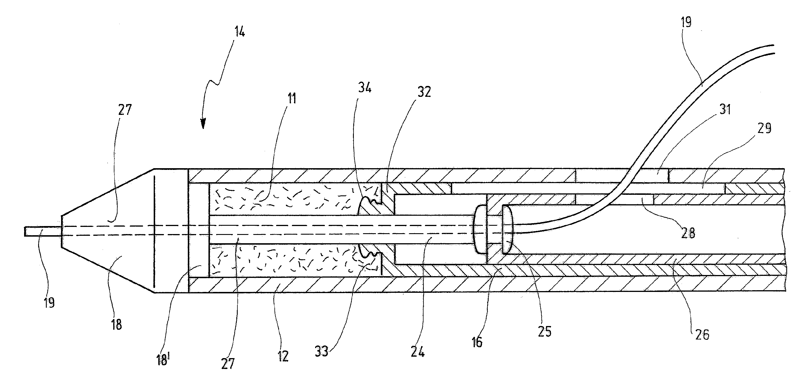
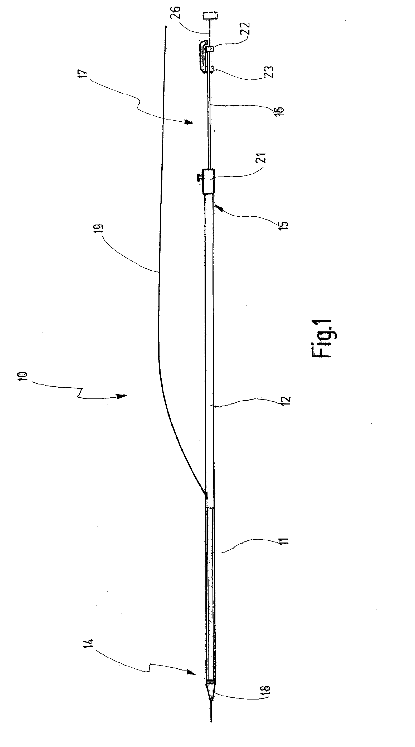
[0085]In FIG. 1, reference number 10 schematically designates a delivery system with which a braided stent, indicated by reference number 11, can be implanted into a blood vessel.

[0086]The braided stent 11 is a self-expanding metal stent produced by a plain weaving technique, as is described in aforementioned DE 103 35 649. Because of its braid angle of α=10°, the braided stent 11, in the state when loaded into the delivery system 10 as shown in FIG. 1, has a length that is about five times longer than the length of the braided stent in the released state.

[0087]The delivery system 10 comprises an outer sleeve 12, on the distal end 14 of which the braided stent 11 is arranged, and an opposite proximal end 15.

[0088]In line with conventional terminology, distal direction designates a direction which is toward the patient and in which the braided stent 11 is to be implanted. Proximal direction accordingly designates a direction toward the operator.

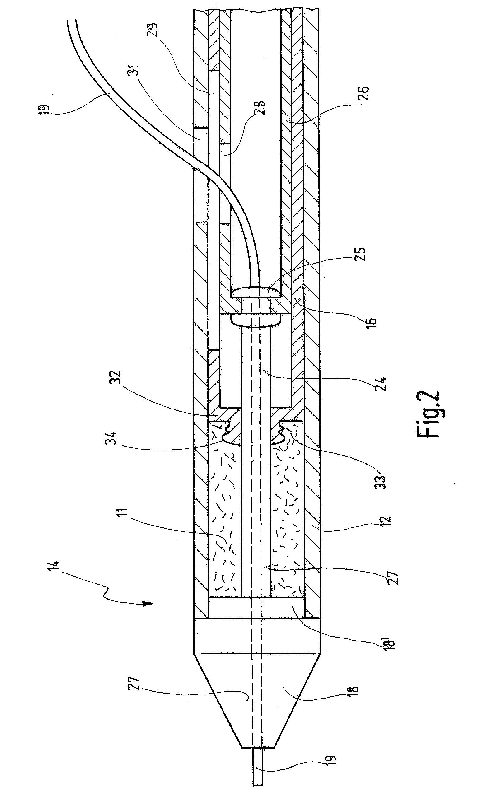
[0089]An inner sleeve 16 is arranged in...


PUM


Abstract

An insertion system with a self-expanding braided stent (11) for implantation in a blood vessel has an outer sleeve (12) with a distal end (14) and a proximal end. An inner sleeve (16) arranged in the outer sleeve (12) is displaceable relative to the latter and protrudes, with a handling section, from the proximal end of the outer sleeve (12). Moreover, at the distal end (15), there is a tip (18) which is securely connected to a stent support (24) on which the braided stent (11) is arranged in its loaded state. The stent support (24) is arranged to be displaceable relative to the inner sleeve (16).

Description

CROSS REFERENCE TO RELATED APPLICATIONS[0001]This is a continuation application of International Patent Application PCT / EP2006 / 004026, filed Apr. 28, 2006, designating the United States and published in German as WO 2006 / 117167 A1, which claims priority to German application number DE 10 2005 020 785.5, filed May 4, 2005.BACKGROUND OF THE INVENTION[0002]1. Field of the Invention[0003]The present invention relates to a delivery system having a self-expanding braided stent intended for implantation into a blood vessel, with an outer sleeve, which has a distal end and a proximal end and in which an inner sleeve is arranged that is displaceable relative to the outer sleeve and protrudes, with a handling portion, from the proximal end of the outer sleeve, and with a tip, which is arranged at the distal end and is securely connected to a stent support on which the braided stent is arranged in its loaded state.[0004]2. Related Prior Art[0005]A delivery system of this kind is known commerci...

Claims


Application Information

Patent Timeline
IPC IPC(8): A61F2/06A61F2/90A61F2/95A61F2/966
CPCA61F2/90A61F2/95A61F2/966
Inventor KAUFMANN, RALFHAUSER, BERTHOLD
Owner JOTEC
Why Eureka
Try Eureka