System and Method For Monitoring The Effectiveness Of A Brake Function In A Powered System

a technology of brake function and power system, which is applied in the direction of braking components, process and machine control, electrical devices, etc., can solve the problems of not being able to fully failsafe in application, requiring additional time to activate, and faster response time, so as to determine the performance capability maintain the availability and effectiveness of the dynamic braking system

Active Publication Date: 2008-11-20
GE GLOBAL SOURCING LLC
View PDF18 Cites 79 Cited by
  • Summary
  • Abstract
  • Description
  • Claims
  • Application Information

AI Technical Summary

Problems solved by technology

Although locomotive dynamic braking systems are the most recently developed, none of these systems are entirely failsafe in application.
For example, dynamic braking systems typically have a faster response time than the train line braking system, which requires additional time to activate and release due to air flow constraints reaching the length of the train.
Unfortunately, conventional systems do not provide information regarding the operation and condition of the dynamic braking system in order to ascertain the performance capability of the dynamic braking system.

Method used


Image

  • System and Method For Monitoring The Effectiveness Of A Brake Function In A Powered System
  • System and Method For Monitoring The Effectiveness Of A Brake Function In A Powered System
  • System and Method For Monitoring The Effectiveness Of A Brake Function In A Powered System

Examples


Embodiment Construction

[0037]Though exemplary embodiments of the present invention are described with respect to rail vehicles, specifically trains and locomotives having diesel engines, embodiments of the invention are also applicable for use in other powered systems, including, but not limited to, off-highway vehicles (such as mine trucks and other mining or construction vehicular equipment), marine vessels, and other transport vehicles such as transport buses and agricultural vehicles.

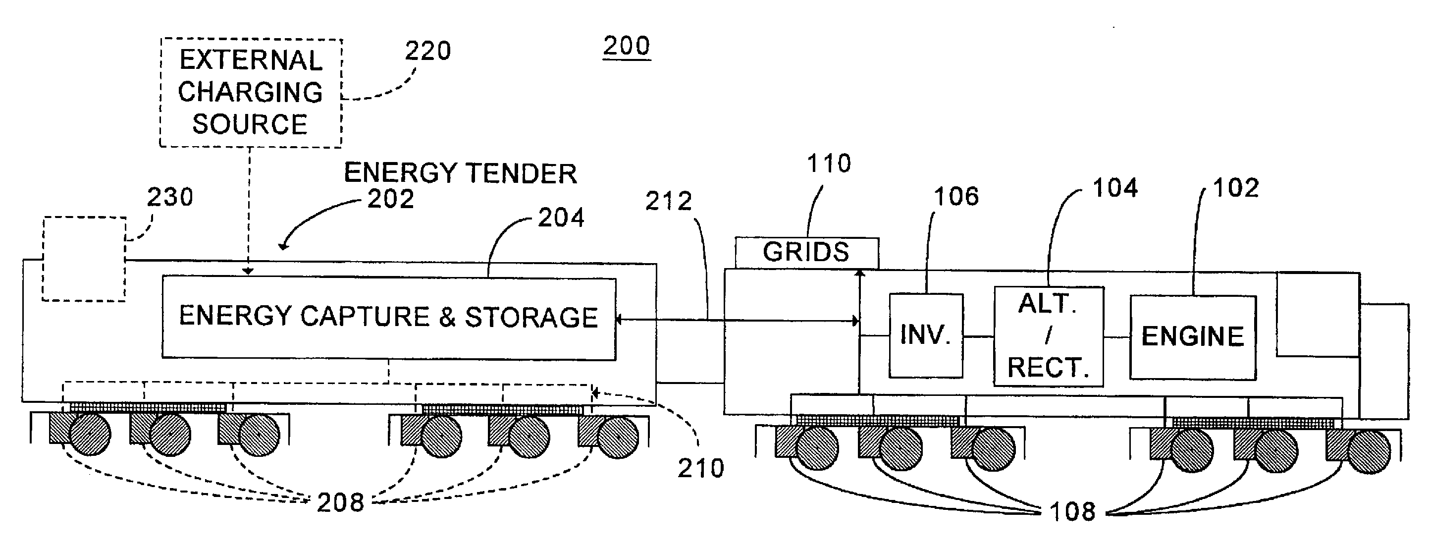
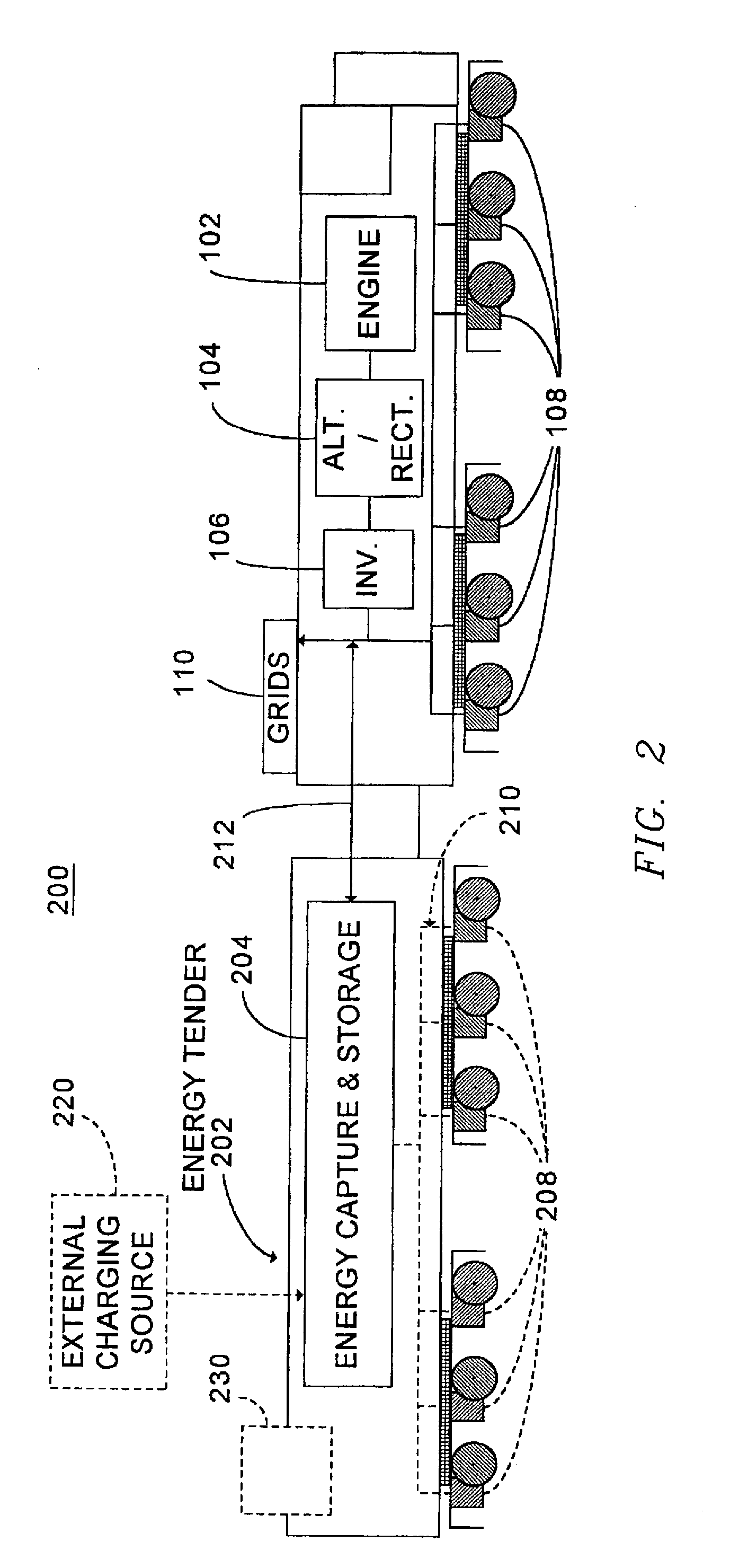
[0038]FIG. 2 is a block diagram of one embodiment of a hybrid energy locomotive system 200. In this embodiment, the hybrid energy locomotive system includes an energy tender vehicle 202 for capturing and regenerating at least a portion of the dynamic braking electric energy generated when the locomotive traction motors operate in a dynamic braking mode. The energy tender vehicle 202 is constructed and arranged to be coupled to the locomotive in a consist configuration, and includes an energy capture and storage system 204...


PUM


Abstract

A system is provided for monitoring the effectiveness of a braking function in a powered system. The system includes a sensor configured to measure a parameter related to the operation of the powered system. Additionally, the system includes a processor coupled to the sensor, to receive data related to the parameter. Subsequent to activating the braking function, the processor is configured to determine the effectiveness of the braking function of the powered system, based upon whether the parameter data varies by a predetermined threshold. A method and a computer software code are also provided for monitoring the effectiveness of a braking function in a powered system.

Description

CROSS-REFERENCE TO RELATED APPLICATIONS[0001]This application claims priority to and is a Continuation-In-Part of U.S. application Ser. No. 11 / 739,864 filed Apr. 25, 2007, and incorporated herein by reference in its entirety.[0002]This application also claims priority to U.S. Provisional Application No. 60 / 988,605 filed Nov. 16, 2007, and incorporated herein by reference in its entirety.BACKGROUND OF THE INVENTION[0003]FIG. 1 is a block diagram of an exemplary prior art powered system, such as a locomotive 100, for example. In particular, FIG. 1 generally reflects a typical prior art diesel-electric locomotive 100. The locomotive 100 includes a diesel engine 102 driving an alternator / rectifier 104. As is generally understood in the art, the alternator / rectifier 104 provides DC electric power to an inverter 106 which converts the AC electric power to a form suitable for use by a traction motor 108 mounted on a truck below the main engine housing. One common locomotive configuration i...

Claims


Application Information

Patent Timeline
Patent Type & Authority Applications(United States)
IPC IPC(8): G01R21/06
CPCB60K6/105B60L2200/26B60L7/18B60L11/123B60L11/1801B60L15/2045B60T17/221B60T17/228Y02T10/6204Y02T10/6217Y02T10/7005Y02T10/7077Y02T10/7283Y10S903/903B60K6/20B60L50/53B60L50/61Y02T10/62Y02T10/64Y02T10/70Y02T10/72Y02T10/7072
Inventor KUMAR, AJITH KUTTANNAIRSHAFFER, GLENN ROBERTPELTZ, DAVID MICHAELNOFFSINGER, JOSEPH F.
Owner GE GLOBAL SOURCING LLC
Why Eureka
Try Eureka