Fluid Pressure Pulsation Damper Mechanism and High-Pressure Fuel Pump Equipped with Fluid Pressure Pulsation Damper Mechanism

a technology of fluid pressure pulsation damper and damper mechanism, which is applied in the direction of machines/engines, fuel injecting pumps, and positive displacement liquid engines

Active Publication Date: 2008-11-27
HITACHI LTD
View PDF9 Cites 90 Cited by
  • Summary
  • Abstract
  • Description
  • Claims
  • Application Information

AI Technical Summary

Benefits of technology

[0014]According to the present invention, the cover is made of a thin metal plate, but the inner convex curved parts have necessary stiffness. In addition, the outer convex curved parts f

Problems solved by technology

The technology described above prior arts has a problem in that the cover is made of a thi

Method used


Image

  • Fluid Pressure Pulsation Damper Mechanism and High-Pressure Fuel Pump Equipped with Fluid Pressure Pulsation Damper Mechanism
  • Fluid Pressure Pulsation Damper Mechanism and High-Pressure Fuel Pump Equipped with Fluid Pressure Pulsation Damper Mechanism
  • Fluid Pressure Pulsation Damper Mechanism and High-Pressure Fuel Pump Equipped with Fluid Pressure Pulsation Damper Mechanism

Examples


first embodiment

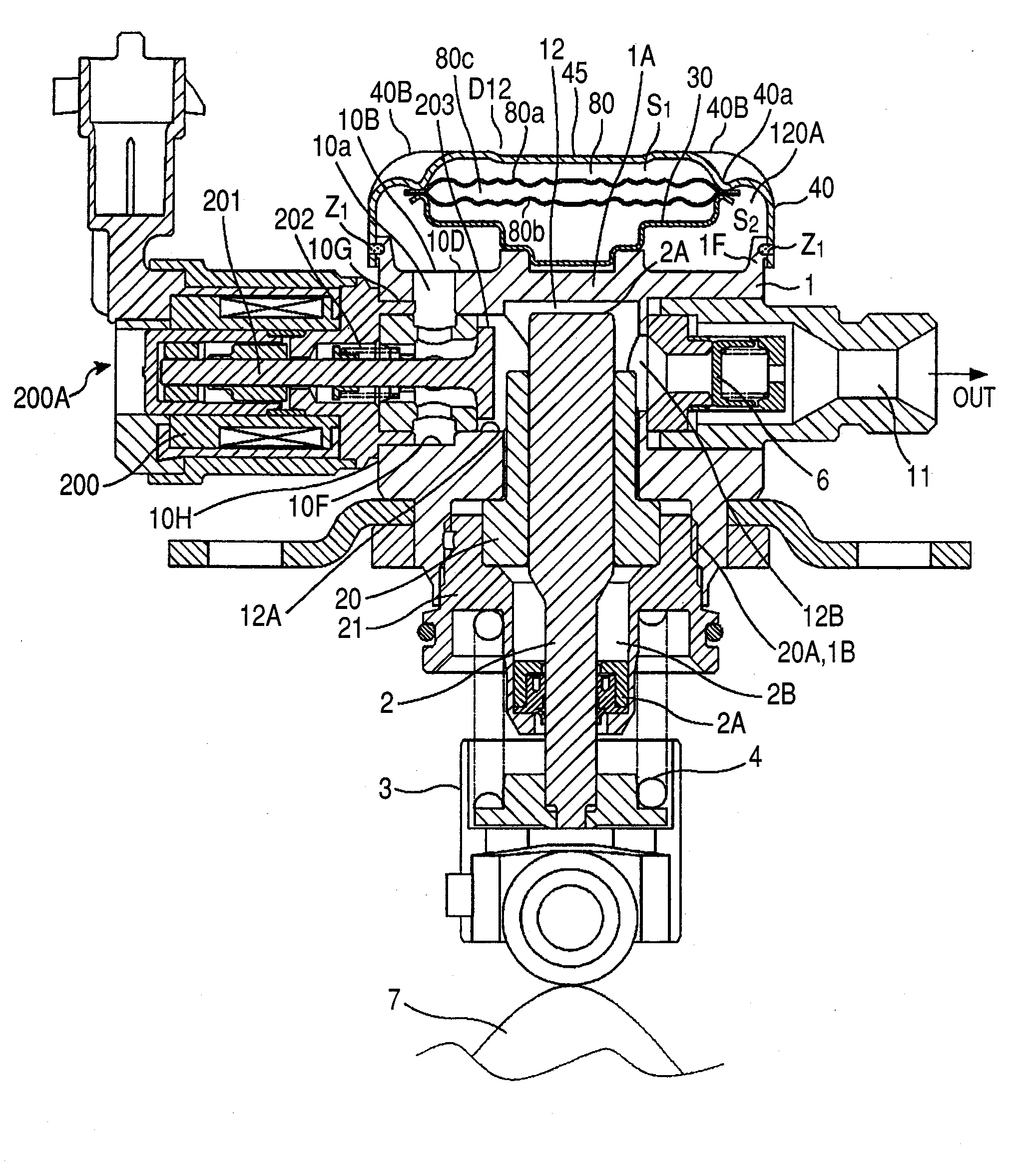
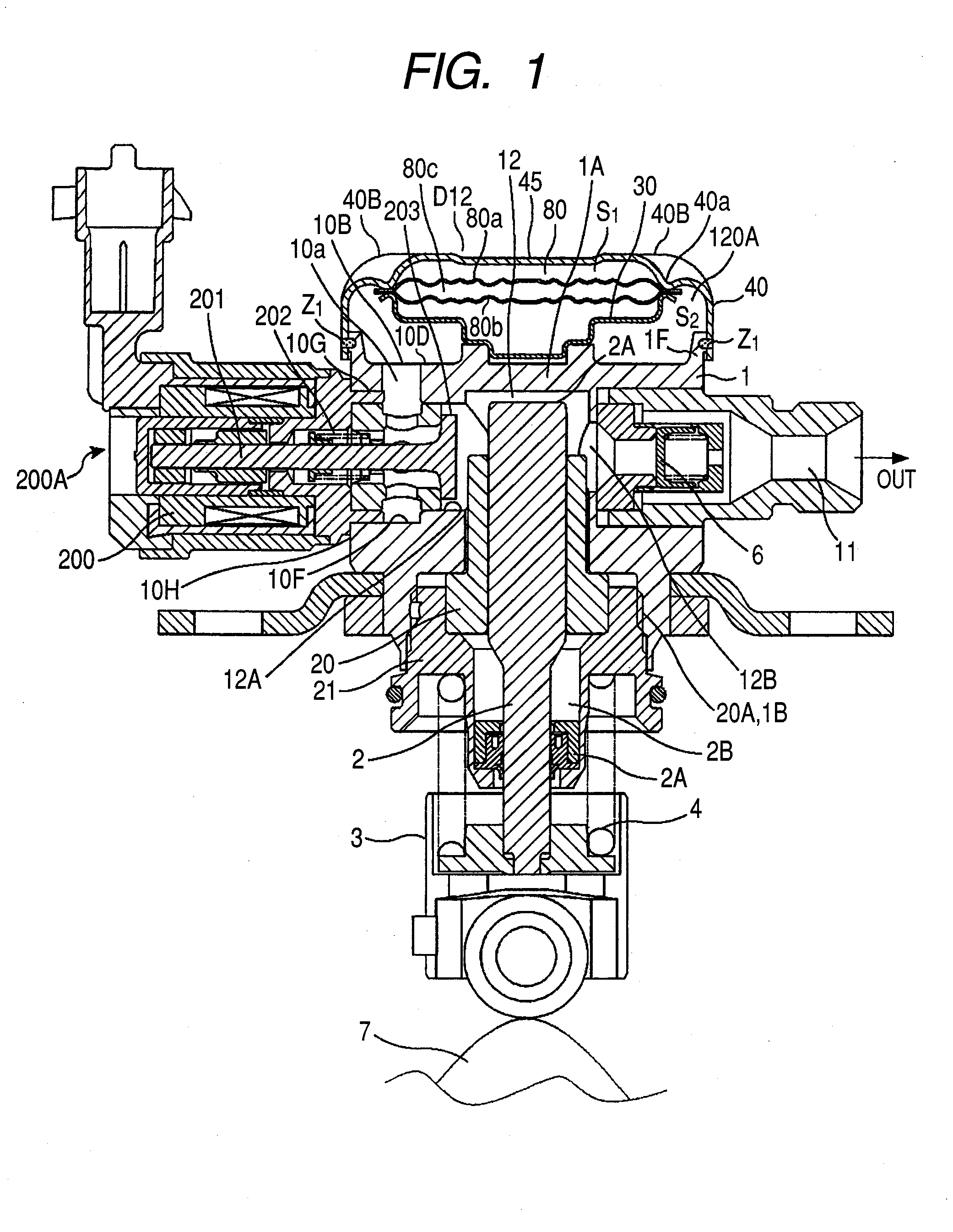
[0036]FIG. 12 is a longitudinal cross sectional view of a fluid pressure pulsation damping mechanism in a first embodiment of the present invention.

[0037]The metal damper 120 in the fluid pressure pulsation damping mechanism D12 comprises two metal diaphragms 121 and 122, between which there is a sealed spacing 123 filled with a gas.

[0038]An edge part 124 of the metal damper 120 is formed by overlapping the peripheries of the two metal diaphragms 121 and 122; welding is performed over the entire peripheries of the outer edge 125 of the edge part 124, maintaining a hermetic seal inside the sealed spacing 123.

[0039]A damper housing part 120A accommodates the metal damper 120, and its frame 127 is formed on the outer surface of a main body 126.

[0040]The frame 127 on the main body 126 is ring-shaped; the internal periphery of a skirt 129 of a cover 128 fits into the outer periphery of the frame 127 of the main body 126, and the damper housing part 120A is formed by welding their entire ...

second embodiment

[0055]In a fluid pressure pulsation damping mechanism in a second embodiment shown in FIG. 13, a fluid inlet channel 126A is formed at the center of the main body 126; a hole 126a, which is linked to the fluid inlet channel 126A and open to the damper housing part 120A, is formed at the center of an extrusion 126P; another hole 133A is also formed at the center of the holding member 133.

[0056]Accordingly, fluid flows from a fluid inlet 126C connected to an upstream pipe at a threaded part 126F through the fluid inlet channel 126A, holes 126a, 133A, and 126b, the fluid outlet channel 126B, and fluid outlet 126D, to a downstream pipe connected at a threaded part 126G.

third embodiment

[0057]A fluid pressure pulsation damping mechanism in a third embodiment shown in FIG. 14 indicates that an O-ring 126H can be applied to a connection part of the fluid inlet 126C to which the upstream pipe is connected.


PUM


Abstract

A fluid pressure pulsation damper mechanism comprising: a metal damper having two metal diaphragms joined together with a hermetic seal for forming a sealed spacing filled with a gas between the two metal diaphragms, an edge part at which are overlapped along outer peripheries thereof; a main body having a damper housing in which the metal damper is accommodated; and a cover attached to the main body to cover the damper housing and isolate the damper housing from an outside air, the metal damper being held between the cover and the main body; wherein the cover is further comprising: a metal plate for making the cover, a peripheral edge of the cover being joined to the main body, a plurality of inner convex curved parts extending toward the main body and a plurality of outer convex curved parts extending in a direction away from the main body, and a plurality of the inner convex curved parts and a plurality of the outer convex parts being disposed alternately inside the peripheral edge of the cover at which the cover is joined to the main body; wherein the cover is attached to the main body, ends of the plurality of inner convex curved parts touch one side of the edge part of the metal damper, which are outwardly formed in radial directions of a part including the sealed spacing in the metal damper; and the metal damper is held between the cover and a metal damper holding part of a holding member placed on the main body.

Description

CLAIM OF PRIORITY[0001]The present application claims priority from Japanese application serial No. 2007-133612, filed on May 21, 2007, the content of which is hereby incorporated by reference into this application.BACKGROUND OF THE INVENTION[0002]1. Field of the Invention[0003]The present invention relates to a fluid pressure pulsation damper mechanism, and more particularly to a fluid pressure pulsation damper mechanism in which a metal damper is disposed between a main body and a cover attached to the main body and thereby held, the metal damper being formed by joining two metal diaphragms and filling a gas between them.[0004]The present invention also relates to a high-pressure fuel pump that is equipped with the above fluid pressure pulsation damper mechanism and used with an internal combustion engine.[0005]2. Description of Related Art[0006]With known conventional fluid pressure pulsation damper mechanisms of this type, two metal diaphragms are joined by being welded along th...

Claims


Application Information

Patent Timeline
IPC IPC(8): F16L55/04
CPCF02M55/04F02M59/102F02M59/366F02M59/367F02M59/48F02M63/0225F02M2200/315F04B11/0016
Inventor MUNAKATA, AKIHIROMACHIMURA, HIDEKIYAMAUCHI, HIDEAKIKITAJIMA, DAISUKENEMOTO, MASASHI
Owner HITACHI LTD
Why Eureka
Try Eureka