
Instrumented joint system

a joint system and instrument technology, applied in the direction of instruments, drags, mechanical equipment, etc., can solve the problems of damage to the detection unit, unit can also be subject to knocks, and the earthmoving machine is generally subject to extensive contamination, etc., to achieve the effect of easy fitting and removal, and protection

Inactive Publication Date: 2008-11-27
AB SKF
View PDF8 Cites 14 Cited by
  • Summary
  • Abstract
  • Description
  • Claims
  • Application Information

AI Technical Summary

Benefits of technology

[0012]More specifically, embodiments described herein are aimed at providing an instrumented joint system which is particularly compact, well protected, easy to fit and to remove, and economical.
[0013]Furthermore, the embodiments described herein provide a system that is highly dependable.
[0015]With a system such as this it then becomes possible for the sleeve and support to be removed particularly easily, thereby limiting the risk of damage to the bearing or bearings.
[0016]Specifically, providing a means of axial retention makes it possible to avoid mounting the support tightly inside the housing. As a result, once the axial-retention means has been removed, the support and the sleeve can be easily extracted from the housing. This then limits the risk of damage to the rolling bearing or bearings when the system is disassembled.
[0017]In other words, with the axial-retention means bearing against the support on which the inner ring of the rolling bearing is mounted and the outer ring of the said bearing mounted in the sleeve which is itself mounted contactlessly in the housing of the pivot pin, it is possible to avoid stressing the bearing excessively when disassembling the system. This is rendered possible, in particular, by the fact that the bearing is mounted without direct contact with the pivot pin.

Problems solved by technology

Now, the earthmoving machine is generally subject to extensive contamination by being sprayed with various contaminants, particularly earth, mud or dust.
Furthermore, this machine is cleaned using high-pressure water jets which are liable to damage the detection unit.
Furthermore, because of the way in which it is arranged on the pivot shaft, the unit can also be subjected to knocks as the plant on which it is mounted moves along.
As a result, it will be readily understood that there is a significant risk of the detection unit becoming damaged, thus appreciably reducing its life and the reliability of the earthmoving machine.
A major disadvantage with this joint system in particular is that it does not allow the unit to be removed easily so that, for example, one of the means designed for detection can be repaired.
The problem is that in order to move the unit once it has been fitted a relatively high axial tensile force has to be exerted on the secondary shaft, and this subjects the rolling bearing to excessive stress and may cause damage to this bearing.

Method used


Image

  • Instrumented joint system
  • Instrumented joint system
  • Instrumented joint system

Examples


Embodiment Construction

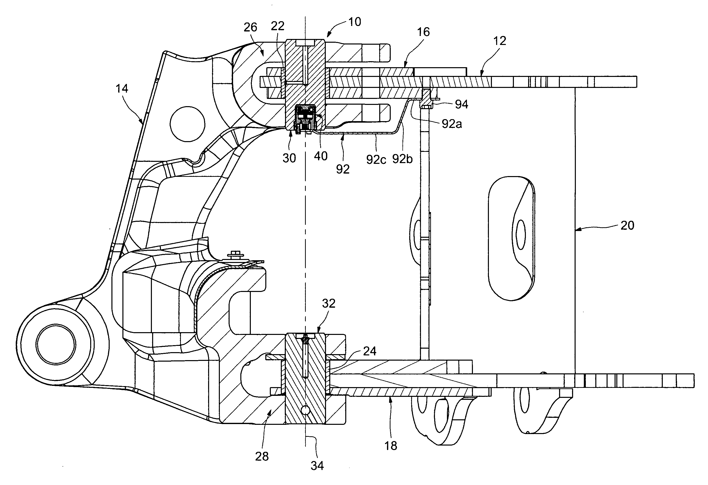
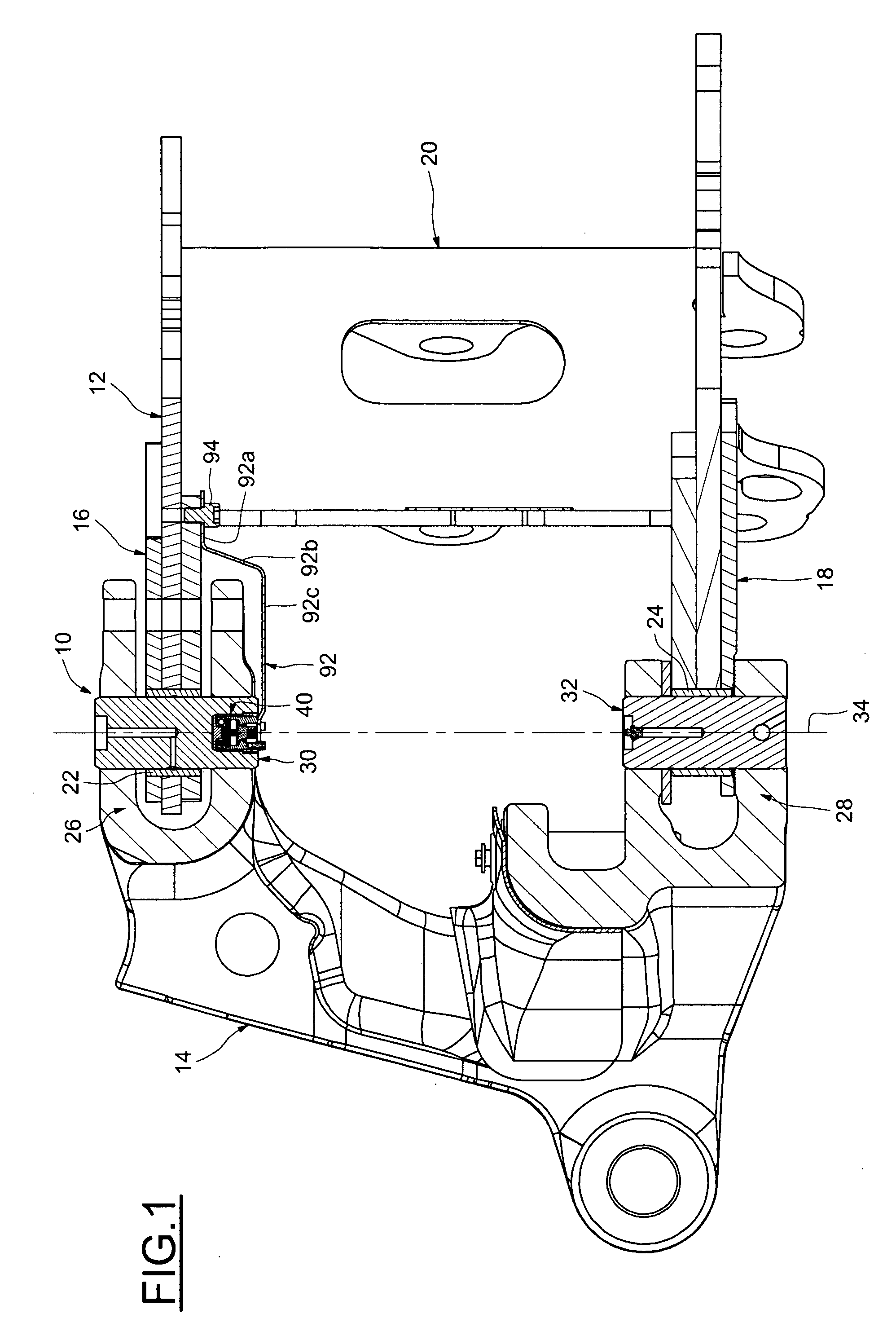
[0033]FIG. 1 depicts an instrumented joint system denoted by the overall numerical reference 10, intended to connect a first part 12, in this instance fixed and secured to a chassis (not depicted) of earthmoving plant and a second part 14 that forms an articulated arm able to move with respect to the first part 12. The plant may, for example, be a power shovel.

[0034]The fixed first part 12 in particular includes two connecting elements 16, 18 which are parallel and joined together by a spacer piece 20 that runs transversely.

[0035]To allow the joint system 10 to be mounted such that it can rotate with respect to the fixed first part 12, the latter also includes plain bearings 22, 24 mounted near the free ends of the connecting elements 16 and 18 respectively.

[0036]The moving second part 14 has, in cross section, the overall shape of a U. Each end of the U includes a clevis 26, 28 surrounding the connecting elements 16 and 18 respectively.

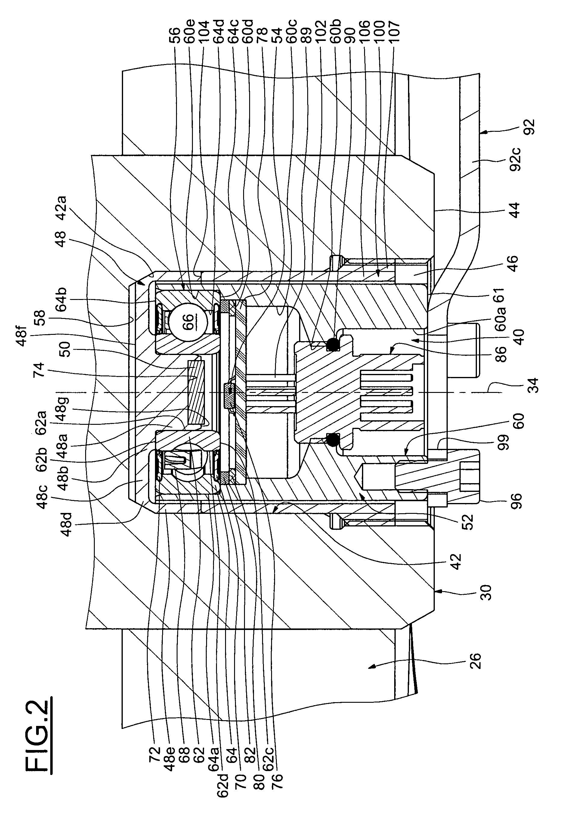
[0037]In order to articulate the moving second...


PUM


Abstract

The instrumented joint system includes a pivot pin capable of connecting a first part and a moving second part that can pivot with respect to the first part, and a detection assembly for detecting rotation parameters of the second part and which is mounted inside a housing of the pivot pin, the said detection assembly including at least one rolling bearing equipped with an inner ring and with an outer ring, and a sleeve angularly connected to the outer ring. The detection assembly is further provided with a support angularly connected to the pivot pin and on which the inner ring of the bearing is mounted, and with a retaining means for retaining the support axially inside the housing.

Description

BACKGROUND OF THE INVENTION[0001]1. Field of the Invention[0002]The present invention relates to the field of instrumented joint systems used in particular on earthmoving machine.[0003]More specifically, the present invention relates to an instrumented joint system intended to connect a first part and a moving second part that can pivot with respect to the first part and which is capable of measuring the relative angular displacement of these two parts.[0004]2. Description of the Relevant Art[0005]Instrumented joint systems are conventionally used on the articulated arms of an earthmoving machine in order to control the angular displacement of various articulated elements.[0006]In general, these joint systems include a detection unit which is attached to one axial end of a pivot shaft connecting two parts, one of which is able to pivot with respect to the other.[0007]Now, the earthmoving machine is generally subject to extensive contamination by being sprayed with various contaminan...

Claims


Application Information

Patent Timeline
IPC IPC(8): A01B35/20
CPCE02F9/006F16C11/04F16C41/00G01D11/245F16C41/007F16C2350/26F16C2233/00
Inventor NIARFEIX, FRANCOISLOCHER, BENOIT
Owner AB SKF
Learn More