Intelligent Manifold and Injection Molding Machine

a manifold and intelligent technology, applied in the field of molding systems, can solve the problems of reducing the overall efficiency and productivity of the molding machine, requiring time and expertise for re-configuration, and affecting the efficiency of the molding machin

Active Publication Date: 2008-11-27
HUSKY INJECTION MOLDING SYST LTD
View PDF10 Cites 29 Cited by
  • Summary
  • Abstract
  • Description
  • Claims
  • Application Information

AI Technical Summary

Benefits of technology

[0012]According to one embodiment, the present disclosure features a hot runner system for use with an injection molding system. The hot runner system may include a manifold comprising a plurality of melt channels including at least one inlet configured to be in fluid communication with a source of molten resin and at least one outlet configured be coupled to at least one nozzle. At least one memory device may be coupled to the manifold and include information pertaining to at least one process control parameter of the injection molding system. The memory device may be configured to transmit a signal to a machine controller associated with the injection molding machine representative of the process control parameter. The memory device may be pre-programmed with processing parameters prior to a first run in an injection molding system (i.e. the memory device may be loaded from the factory already with processing information) or may be programmed after a first run in the injection molding machine system.
[0013]According to another embodiment, the present disclosure features an injection molding system. The injection molding system may including a hot runner manifold comprising a plurality of melt channels including at least one inlet configured to be in fluid communi

Problems solved by technology

More particularly, the transition points are particularly important to preform geometry in heavier preforms where shrinkage is more significant, although it is noted that thin-walled and relatively lightweight preforms (less than about fifty grams) have particular fill control issues especially associated with the geometry and thickness transition between the elongate wall portion and the neck portion of the preform.
Again, such a change would require the injection molding

Method used


Image

  • Intelligent Manifold and Injection Molding Machine
  • Intelligent Manifold and Injection Molding Machine
  • Intelligent Manifold and Injection Molding Machine

Examples


Embodiment Construction

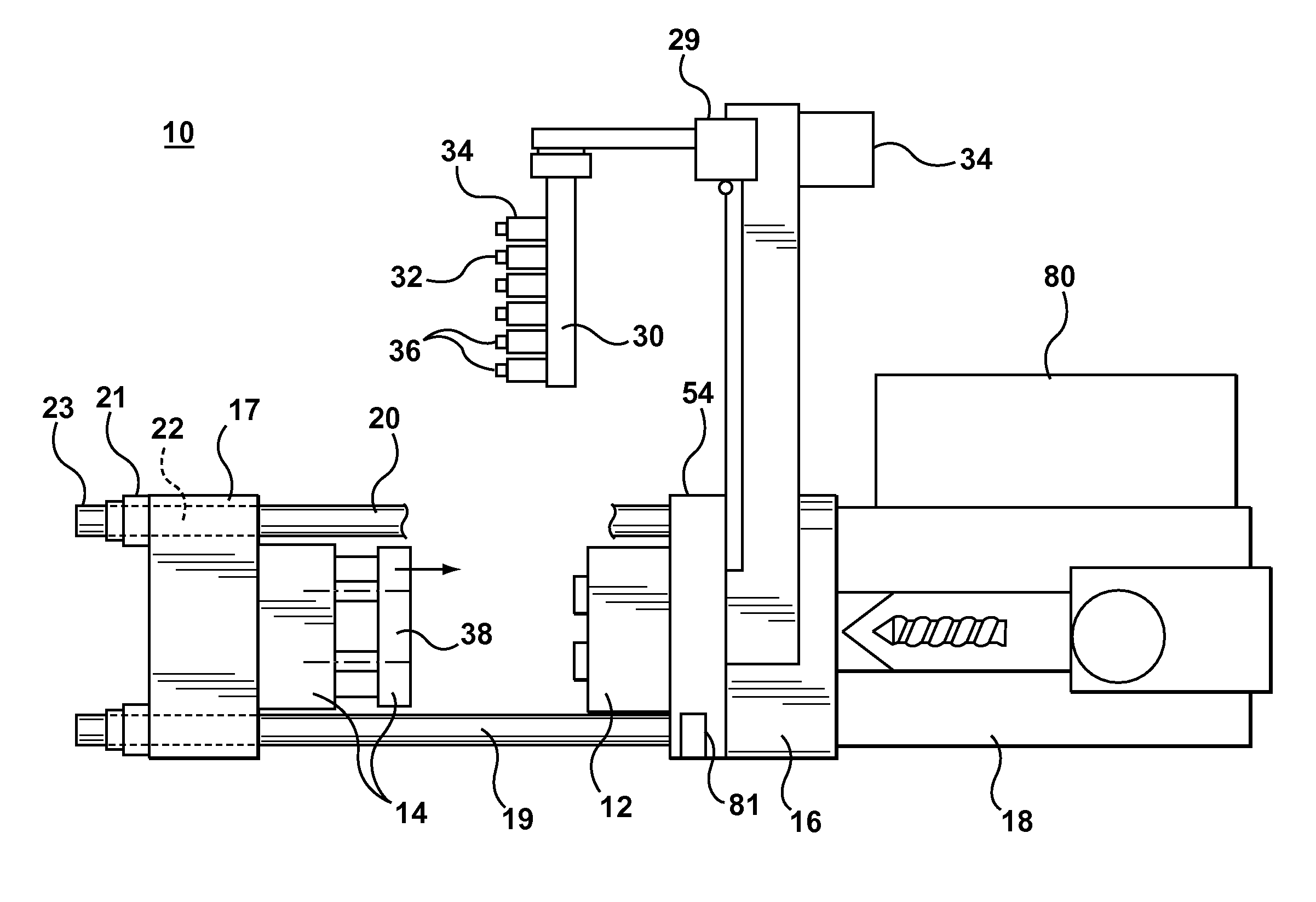
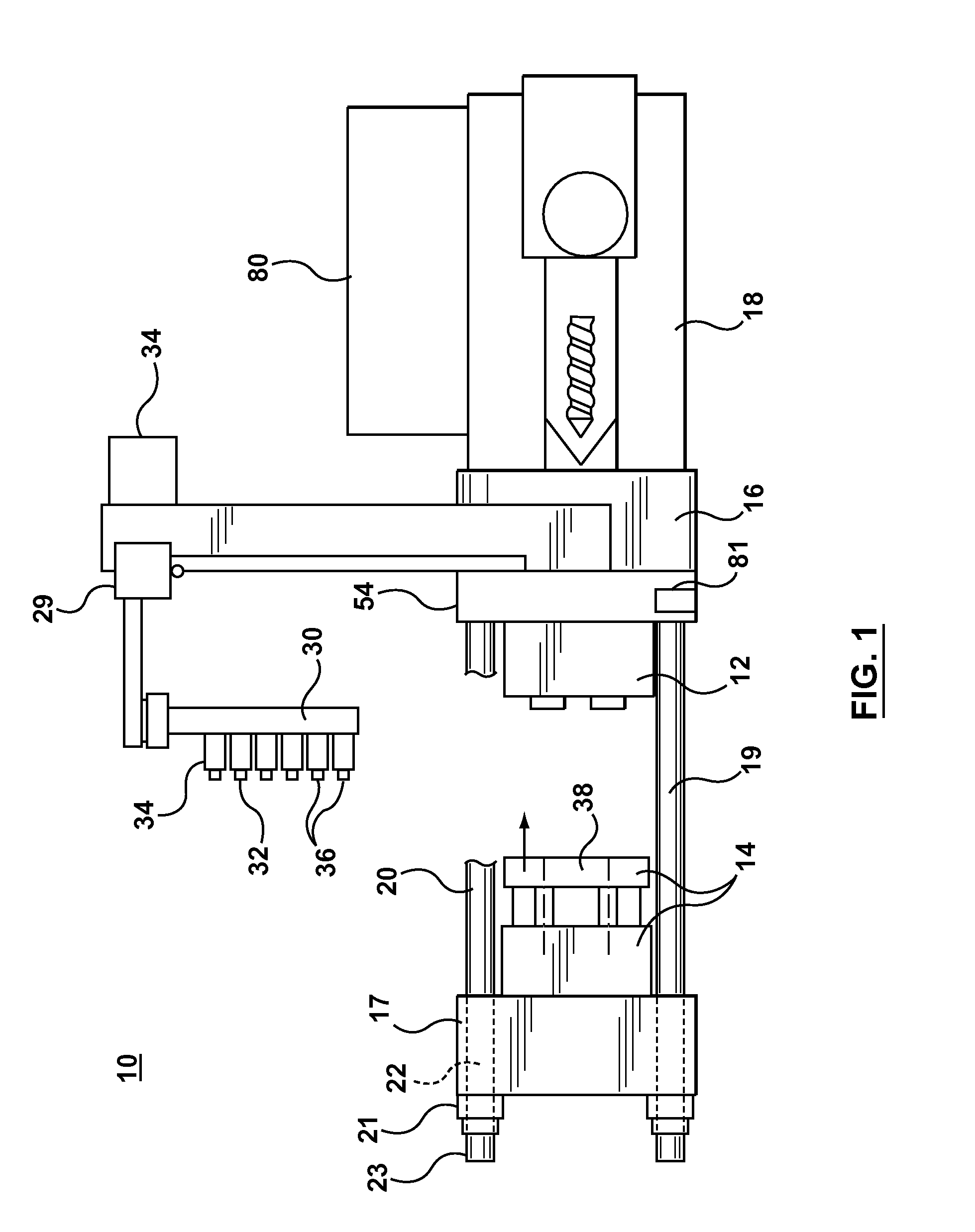
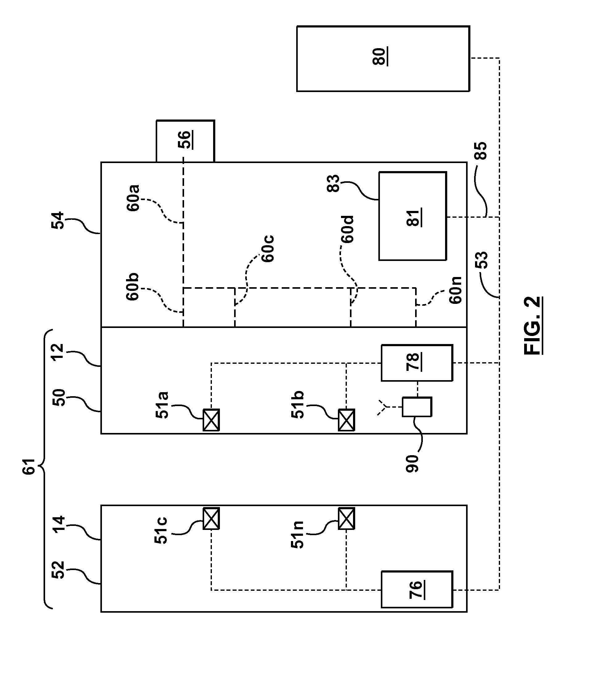
[0019]Referring to FIG. 1, one embodiment of an injection molding machine system 10 according to the present disclosure is shown. As will be explained in greater detail hereinbelow, the injection molding machine system 10 according to the present disclosure may feature a hot runner 54 comprising memory 81 for storing data related to the operation of the injection molding machine system 10 which may be communicated to and used by a machine controller 80 during the operation of the injection molding machine system 10. The hot runner 54 and associated memory 81 may allow a customer to set-up and start the injection molding machine system 10 from a pre-set, optimized process parameter configuration instead of leaving this up to the individual operator. The optimized starting parameters may be pre-programmed based on flow simulation or other simulation methods. Alternatively (or in addition), the memory device 81 may be pre-programmed based on information obtained during a test run in a ...


PUM

PropertyMeasurementUnit
Temperatureaaaaaaaaaa
Flow rateaaaaaaaaaa

Abstract

An injection molding system includes a hot runner comprising a memory device configured to contain at least one process control parameter. The memory device may transmit a signal representative of the process control parameter to a machine controller associated with the injection molding system. The machine controller may generate control signal to operate the injection molding machine based on, at least in part, the signal from the memory device.

Description

TECHNICAL FIELD[0001]The present disclosure relates to molding systems and more particularly, relates to systems and methods for setting up and optimizing the operation of a molding machine.BACKGROUND INFORMATION[0002]In a molding operation, whether this be in an injection molding environment or any similar system using platens and molds, molded part quality and the overall efficiency / productivity of the molding machine is affected by a number of factors, including the physical conditions and configuration of the molding system equipment and also the processing conditions under which the molded part is formed. As a result, proper set-up a molding system may allow the molding system to operate at or near its peak efficiency.[0003]One factor that affects the operation and efficiency of a molding system is setting of the process control parameters. The number and type of process control parameters depends on, at least in part, the configuration of the molding system equipment (for exam...

Claims


Application Information

Patent Timeline
IPC IPC(8): B29C47/92B29C48/92
CPCB29C45/2725B29C47/92B29C2045/1796B29C45/766B29C2945/76993
Inventor BAUMANN, MARTIN
Owner HUSKY INJECTION MOLDING SYST LTD
Why Eureka
Try Eureka