
Split Mounting Type Square Column Assembly

a square column and mounting plate technology, applied in the direction of other domestic objects, walls, show shelves, etc., can solve the problems of personal injury and potential safety hazards, and achieve the effect of improving safety and reliability of exhibition equipment and facilitating the assembly of exhibition equipmen

Inactive Publication Date: 2008-11-27
LINGTONG EXHIBITION SYST
View PDF50 Cites 1 Cited by
  • Summary
  • Abstract
  • Description
  • Claims
  • Application Information

AI Technical Summary

Benefits of technology

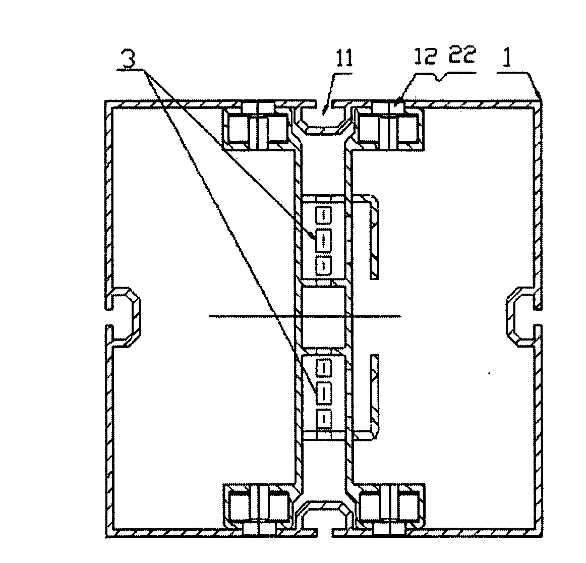
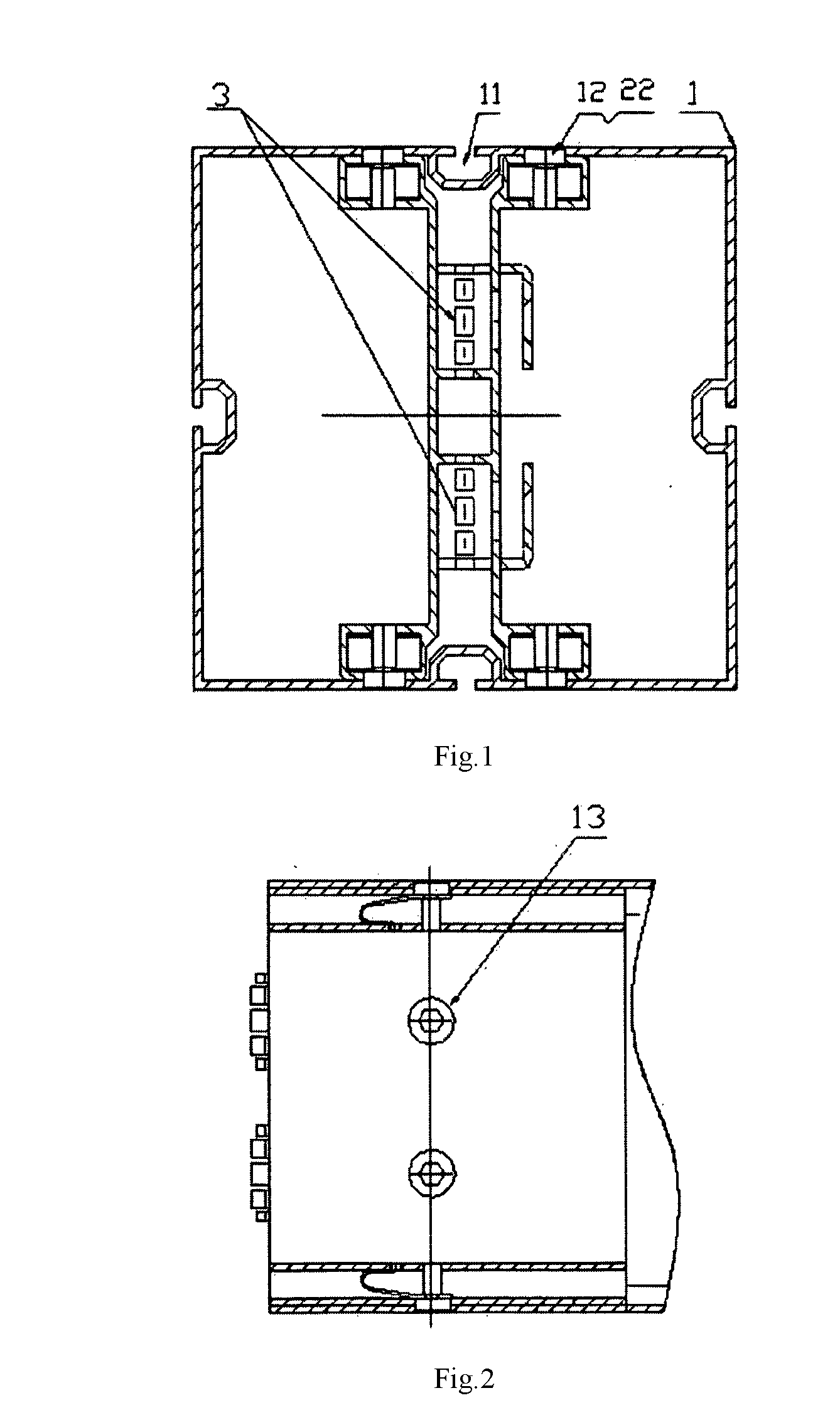
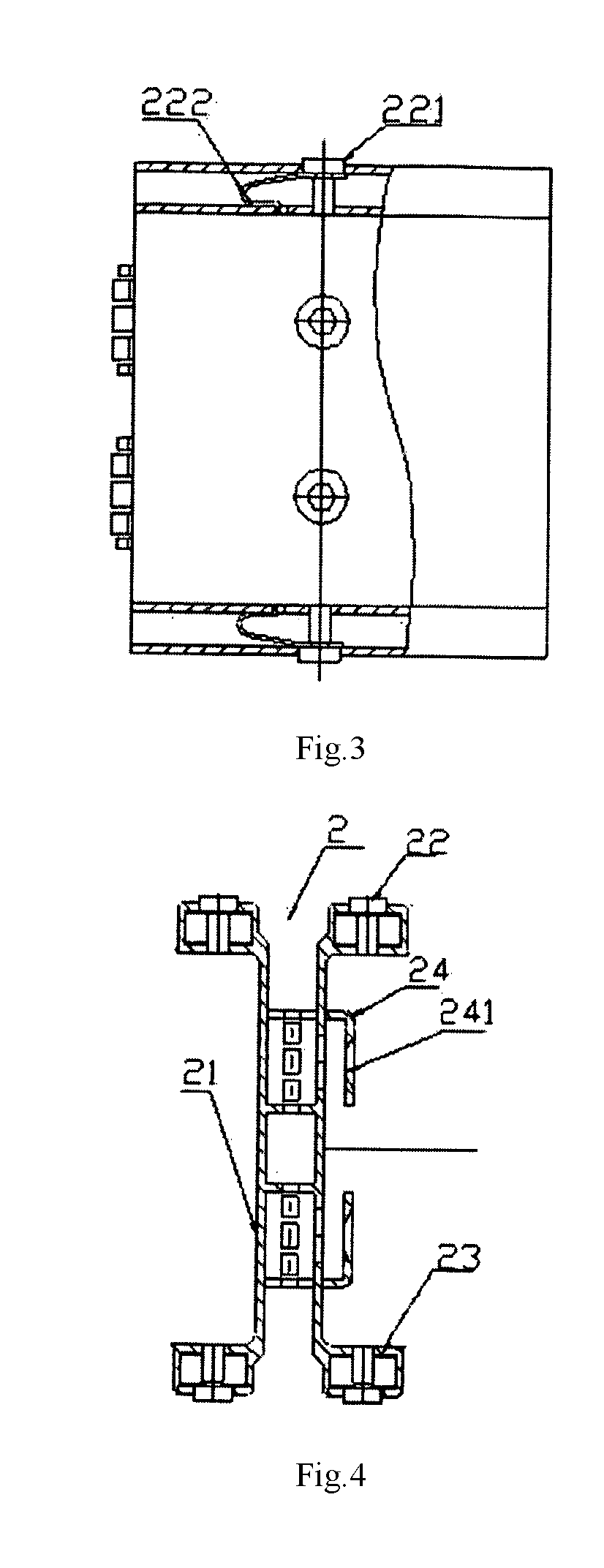
"The present invention provides a split mounting type square column assembly for exhibition equipment that improves safety and reliability. The assembly includes a square column, an embedded type supporting frame, and a connecting lock. The connecting lock is removable and located in the embedded type supporting frame. The embedded type supporting frame is removable located in the square column. The square column has a connecting groove and positioning mounting holes on its outside surface. The embedded type supporting frame has a supporting frame body, a spring cotter, and a spring keyway. The spring cotter is located on the spring keyway and can pass through the positions of the positioning mounting holes when the embedded supporting frame is pushed in or out. The invention ensures completeness or integrity of the connecting groove, so the connection can be implemented at any position. The plates that constrain the square column are removable connected, making assembly easier. The invention employs a spring pin for connection, which ensures required accuracy and maximizes appearance perfection. The mounting point of the structure is above or below the joint, avoiding adverse effect on finishing work on left and right surfaces at the joint."

Problems solved by technology

However, since the retaining screws must have countersunk heads, which must pass through existing grooves to implement tightening, the grooves have to be cut partially to enable the screws to pass through; as the result, there is a potential safety hazard, i.e., if the Operation points of forepaws of connectors in other adjacent supports are right in the cut part of the groove, the connection points are not connected actually or false connected.
For exhibition supports, the consequence may be connection failure of the supporting structure and may result in personal injury.

Method used


Image

  • Split Mounting Type Square Column Assembly
  • Split Mounting Type Square Column Assembly
  • Split Mounting Type Square Column Assembly

Examples


Embodiment Construction

[0016]A split mounting type square column assembly for exhibition equipment, comprising a square column 1, a embedded type supporting frame 2, and a connecting lock 3; wherein, said connecting lock 3 is removable located in said embedded type supporting frame 2; said embedded type supporting frame 2 is removable located in said square column 1, at least one outside surface of said square column 1 has a connecting groove 11, and a quantity of positioning mounting holes 12 is arranged outside of the area of connecting groove 11 on outside surface of said square column 1; said embedded type supporting frame 2 comprises a supporting frame body 21, a spring pin 22, and a spring keyway 23; said spring pin 22 is located on said spring keyway 23; in the initial state, said spring pin 22 overhangs from said spring keyway 23, said spring keyway 23 is located on said supporting frame body 21, therefore the moving pathway of said spring cotter 22 could pass through the positions of said positio...


PUM


Abstract

The present invention relates to a split mounting type square column assembly for the exhibition equipment, comprising a square column, a embedded type supporting frame, and a connecting lock, wherein the said connecting lock may be removable located within the said embedded type supporting frame, and the said embedded type supporting frame may be removable located within the said square column. One outside surface of the said square column at least has a connecting groove, and has a quantity of positioning mounting holes in the area except for the situation of the said connecting groove. Said embedded type supporting frame consists of a supporting frame body, a spring cotter and a spring keyway, wherein, said spring cotter is located within the said spring keyway, and in the initial state, said spring cotter overhangs from the said spring keyway, said spring keyway is located on the said supporting frame body, therefore the moving pathway of said spring cotter could pass through the positions of said positioning mounting holes when said embedded type supporting frame is pushed in or out.

Description

FIELD OF THE INVENTION[0001]The present invention relates to an assembly of combined type exhibition equipment, particularly to a split mounting type square column assembly.BACKGROUND OF THE INVENTION[0002]The prior art employs guide rails in square columns and internally assembled connecting pieces. The connecting pieces are fixed by screw fastening. However, since the retaining screws must have countersunk heads, which must pass through existing grooves to implement tightening, the grooves have to be cut partially to enable the screws to pass through; as the result, there is a potential safety hazard, i.e., if the Operation points of forepaws of connectors in other adjacent supports are right in the cut part of the groove, the connection points are not connected actually or false connected. For exhibition supports, the consequence may be connection failure of the supporting structure and may result in personal injury.SUMMARY OF THE INVENTION[0003]The present invention provides a s...

Claims


Application Information

Patent Timeline
Patent Type & Authority Applications(United States)
IPC IPC(8): A47F5/00
CPCA47F5/00E04B2/766E04B2/7818E04H1/1272
Inventor CHENG, DAOGUANG
Owner LINGTONG EXHIBITION SYST
Learn More