Compact Objective Lens Assembly

a compact, lens technology, applied in the direction of mountings, mirrors, instruments, etc., can solve the problems of inability to choose the firing position of the weapon of the soldier, the telephoto lens is not suited for applications requiring small relative aperture and large field of view, and the problem of forward projection

Active Publication Date: 2008-11-27
DRS NETWORK & IMAGING SYST
View PDF14 Cites 79 Cited by
  • Summary
  • Abstract
  • Description
  • Claims
  • Application Information

AI Technical Summary

Benefits of technology

[0013]Optical systems and assemblies consistent with the present invention provide a compact objective lens assembly suitable for use in helmet-mounted applications. The objectiv...

Problems solved by technology

However, the conventional VNIR and LWIR cameras each have an image-forming optical systems or objective lens assembly that is typically too long in a field-of-view axis to be suitable for use in hand-held, weapon-borne and helmet-mounted applications.
For example, this forward projection problem can inhibit a soldier's choice of weapon firing positions.
Unfortunately, telephoto lenses are not suited for applications requiring small relative apertures and large fields of view because they are prone to sizeable residuals of a backward curving field and both axial and lateral chromatic aberration.
When such an objective lens assembly is combined with an electronic camera, the overall optical path inclusive of the objective lens and camera body is too long (in the direction perpendicular to the camera focal plane array) for the helmet-mounted application, causing the forward projection problem discussed above.
However, this conventional optical system with electronic camera attached is neither satisfactorily thin n...

Method used


Image

  • Compact Objective Lens Assembly
  • Compact Objective Lens Assembly
  • Compact Objective Lens Assembly

Examples


example 1

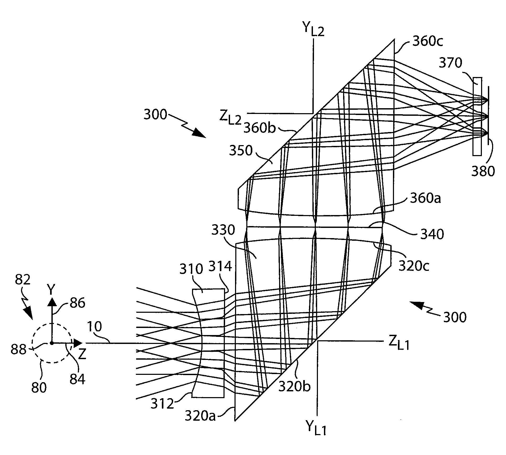
[0061]As discussed above, FIG. 3 depicts a sectional view of one embodiment of an objective lens assembly 300 operatively configured for long-wave infrared imaging consistent with the present invention. As shown in FIG. 3, the sectional view is taken along a YZ plane of the objective lens assembly 300 having a body coordinate system aligned with the coordinate axes 82 of the object 80. The objective lens assembly 300 has, in sequence of light propagation from the object 80, a negative (or diverging) power field lens 310 having a first surface 312 and a second surface 314, a first right angle prism with positive (or converging) power 330, an aperture stop 340, and a second positive power right angle prism 350. As shown in FIG. 3, the second prism 350 is aligned with a plane parallel plate 370, which represents the window of a micro-bolometer camera (e.g., LWIR camera 3300 in FIG. 31), and an image or focal plane array 380 of the micro-bolometer camera that receives an image transferr...

example 2

[0065]FIG. 7 depicts a sectional view of a second embodiment of an objective lens assembly 700 operatively configured for long-wave infrared imaging consistent with the present invention. As shown in FIG. 7, the sectional view is taken along a YZ plane of the objective lens assembly 700 having a body coordinate system aligned with the coordinate axes 82 of the object 80. The objective lens assembly 700 comprises a negative (or diverging) power field lens 710 having a first surface 712 and a second surface 714, a first right angle prism 730, a second positive (or converging) power lens 750 having a first transmitting surface 752 and a second transmitting surface 754, an aperture stop 740, a third positive (or converging) power lens 770 having a first transmitting surface 772 and a second transmitting surface 774, and a second right angle prism 790. The second prism 790 is aligned with a plane parallel plate or window 370, which represents the window of a micro-bolometer camera (e.g.,...

example 3

[0068]FIG. 10 depicts a sectional view of a third embodiment of an objective lens assembly 1000 operatively configured for long-wave infrared imaging consistent with the present invention. As shown in FIG. 10, the sectional view is taken along a YZ plane of the objective lens assembly 1100 having a body coordinate system aligned with the coordinate axes 82 of the object 80. The objective lens assembly 1000 comprises, in the order in which light rays from the object propagate through the lens assembly 1000, a negative (or diverging) power meniscus lens 1010 having a first surface 1012 and a second surface 1014, a first right angle prism 1030, a second right angle prism 1050, a second negative power meniscus lens 1070 having a first surface 1072 and a second surface 1074, an aperture stop 1060, and two positive power lenses 1090 and 1100. In the implementation shown in FIGS. 10-12, the first 1090 of the two power lenses 1090 and 1100 has a front planar surface 1092 and a rear convex s...


PUM


Abstract

A high-performance image-forming optical objective lens made compact and thin, particularly in the object side direction, by twice folding the optical path by means of two prism lenses longitudinally separated and arranged in an angular relationship to one another. The prisms have entrance and exit faces each of which is constructed of a curved surface having optical power, as well as having a rotationally symmetric polynomial aspheric attribute. The image-forming optical objective is particularly suited to helmet-mounted applications wherein the angular means for folding the optical path provides for an optical objective configuration that closely conforms to the exterior surface contour of the helmet, while providing a minimal forward projection in object space from the helmet.

Description

FIELD OF THE INVENTION[0001]The present invention relates to image-forming optical systems for applications in the visible, near infrared and thermal infrared regions of the electromagnetic spectrum. In particular, the present invention relates to an objective lens assembly having two prisms longitudinally separated relative to a structure (such as a helmet or other headgear), and arranged in an angular relationship to one another such that an optical path through the system is folded to conform to a surface of the structure and to minimize a length of the optical path along an axis perpendicular to the structure surface.BACKGROUND OF THE INVENTION[0002]With the advent of small, low power stand-alone electronic type cameras for the detection of visible, near-infrared (VNIR) and long-wave infrared (LWIR) images (such as the conventional image-intensified CMOS imager for VNIR image detection and the uncooled micro-bolometer focal plane array imager for LWIR image detection), the numbe...

Claims


Application Information

Patent Timeline
IPC IPC(8): G02B17/08G02B13/14
CPCG02B7/002G02B13/146G02B17/0856G02B17/0896G02B27/0172
Inventor HEIMER, RICHARD J.
Owner DRS NETWORK & IMAGING SYST
Why Eureka
Try Eureka