Bone-Conduction Device and Method of Manufacturing the Same

a bone-conduction speaker and manufacturing method technology, applied in the direction of deaf-aid sets, electrical transducers, transducer details, etc., can solve the problems of cumbersome users, large number of man-hours needed to produce the parts of the conventional bone-conduction speaker, and significantly impair the productivity of the conventional speaker. , to achieve the effect of improving the device and the method in productivity, improving the stability of the product, and improving the quality of the produ

Inactive Publication Date: 2008-11-27
TEMCO JAPAN
View PDF1 Cites 4 Cited by
  • Summary
  • Abstract
  • Description
  • Claims
  • Application Information

AI Technical Summary

Benefits of technology

[0014]According to the present invention, the bone-conduction device and the method of manufacturing the device contribute to the stability of product's quality and the reliability of the product, because: it is possible for the present invention to reduce the number of man-hours needed to produce the parts of the device, which improves the device and the method in productivity; any grinding operation is not required in the present invention, so that a cumbersome removal operation of the grinding dust or waste is not required at all in the present invention; and, variations in lowest resonance frequency of the product, which are caused by variations in thickness of the diaphragm, are substantially prevented from occurring, which leads to the improvement in stability of product's quality and the reliability of the product.
[0015]In the case where the diaphragm has its outer end edge or its opposite bent portions laser-welded to the diaphragm fixing portion, any screw set portion is not required. This makes it possible to save a space for the installation of such screw set portions, and therefore makes it possible to downsize the device as a whole. This is one of effects of the present invention.
[0016]In the present invention as set forth in the appended claims 7 to 9, it is possible to set the gap between the diaphragm and the yoke in an easy manner without fail.
[0017]This is one of effects inherent in the present invention.

Problems solved by technology

In such a conventional bone-conduction speaker and the method of manufacturing the same described above, the number of man-hours needed to produce the parts of the conventional bone-conduction speaker is too large.
This considerably impairs the conventional speaker in productivity.
In addition, it is cumbersome for the user to be forced to check the spot-welded portions in mechanical strength by the application of load to the welded portions (by pushing) since it is impossible for the user to check such concealed welded portions through visual inspection.
Furthermore, since the grinding operations are performed after completion of the welding operation of the diaphragm 35, it is hard for the user to control the extent of the grinding operations.
Due to this, the conventional bone-conduction speaker is poor in stability of the product's quality and reliability.
Further, as for removal of the grinding dust or waste produced during the grinding operations, it is difficult to completely remove such dust or waste.
In other words, it takes too much time.
This is one of problems inherent in the conventional bone-conduction device.
However, heretofore there is no proposal on a method for determining the narrow gap in assembly in an easy manner without fail.

Method used


Image

  • Bone-Conduction Device and Method of Manufacturing the Same
  • Bone-Conduction Device and Method of Manufacturing the Same
  • Bone-Conduction Device and Method of Manufacturing the Same

Examples


Embodiment Construction

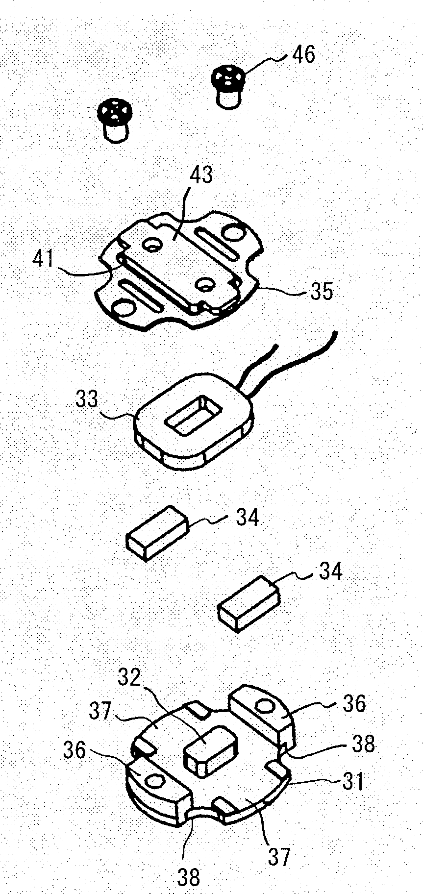
[0018]Preferred embodiments for carrying out the present invention will be described with reference to the accompanying drawings. Incidentally, there is substantially no difference in construction between a bone-conduction speaker and a bone-conduction microphone except that: in the former, a vibrating plate or diaphragm issues its output or bone-conduction vibrations; whereas, in the latter, the vibrating plate or diaphragm picks up the bone-conduction vibrations. Due to this, it should be understood that a bone-conduction device, which will be described in the following description, comprises both the bone-conduction speaker and the bone-conduction microphone.

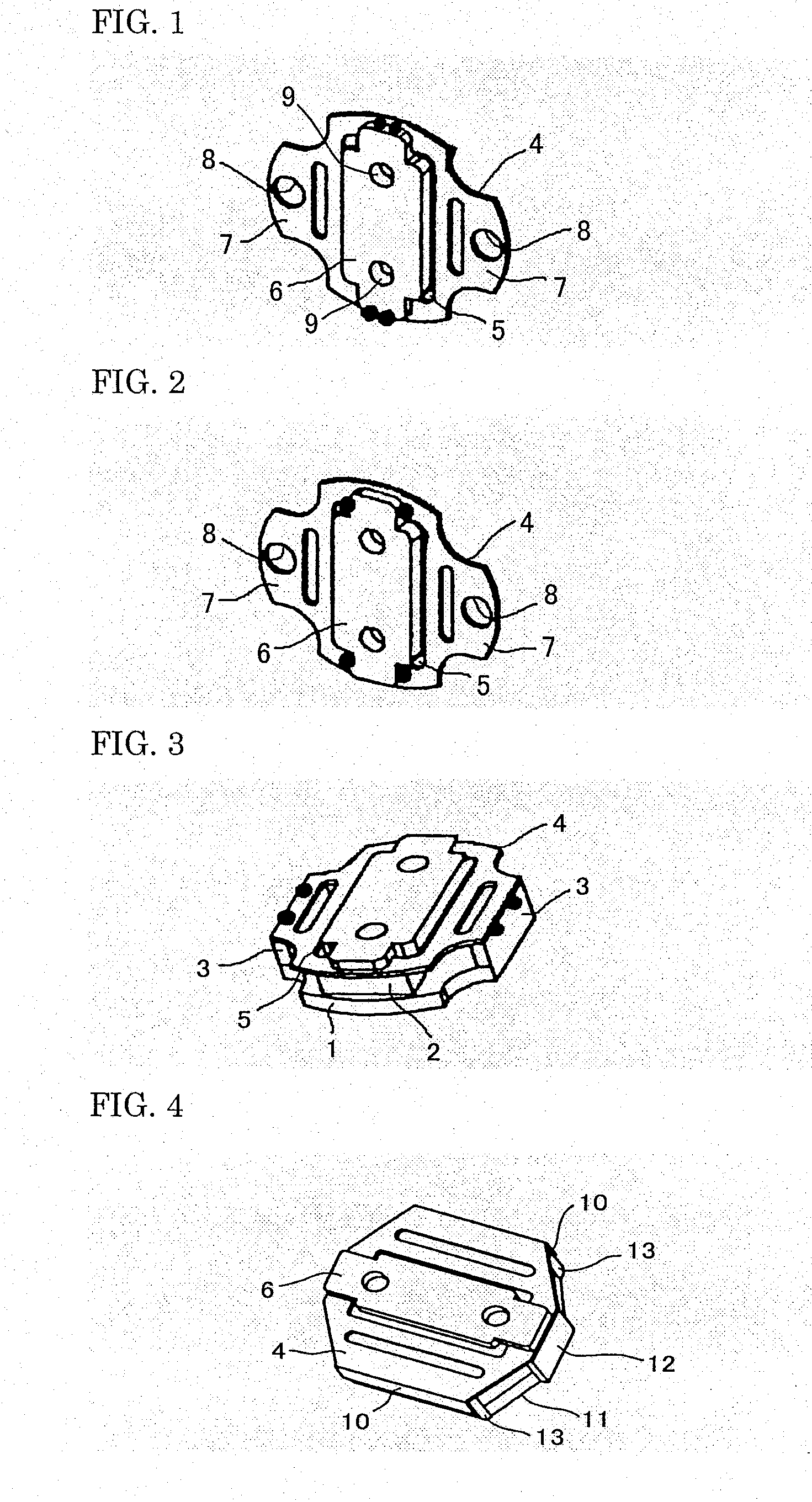
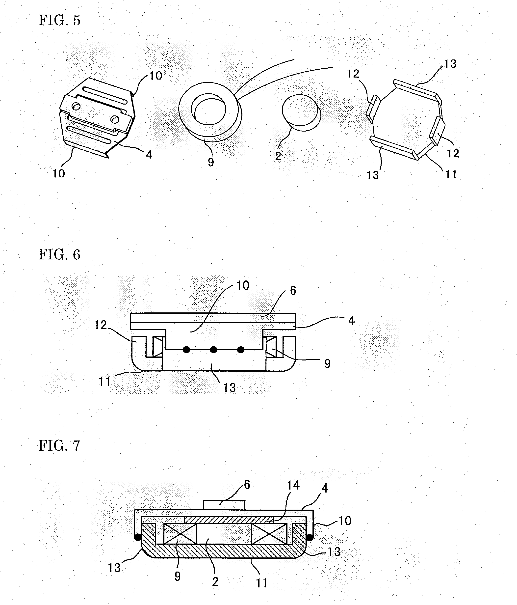
[0019]There is substantially no difference in essential construction between the bone-conduction device of the present invention and the conventional bone-conduction device. In other words, the essential construction is constructed of: a yoke 1 provided with a center pole and a voice coil wrapped around the center pole, the y...


PUM


Abstract

The object is to provide a bone-conduction speaker and its manufacturing method, wherein: efficiency in production is excellent due to reduction in man-hours needed to produce the speaker's parts; any cumbersome removal operation of grinding dust is eliminated; and, variations in product's lowest resonance frequency derived from variations in diaphragm's thickness are minimized, which contributes to improvement in stability of the product's quality and in reliability of the product. The speaker comprises: a yoke (1) having a center magnetic pole and a voice coil wrapped around the pole; magnets (2) disposed on opposite extensions of the yoke (1); diaphragm fixing portions (3) disposed on the other opposite extensions of the yoke (1); the diaphragm (4) fixed to the fixing portions (3); and a plate yoke (6) fixed to the diaphragm (4) to which the yoke (6) has its outer peripheral edges adjacent to the fixing portions (3) laser-welded.

Description

TECHNICAL FIELD[0001]The present invention relates to a bone-conduction device and a method of manufacturing the bone-conduction device, and more particularly to a bone-conduction device and a method of manufacturing the bone-conduction device, which comprises a bone-conduction speaker and a bone-conduction microphone each compact in construction and manufactured in an easy manner.BACKGROUND ART[0002]One of bone-conduction speakers known in the art is shown in FIGS. 8-10 (see Japanese Patent No, 2967777). This one comprises a voice coil 33 wrapped around a center magnetic pole 32, which forms a portion of a yoke 31. The yoke 31 is provided with 4 pieces of extensions 37, 38 each extending outward from the yoke 31 in each of four different directions. Of these four extensions, each of opposite extensions 37, 37 is provided with a magnet 34 disposed thereon. On the other hand, the other opposite extensions 38, 38 are provided with diaphragm fixing portions 36, 36 each of which forms a...

Claims


Application Information

Patent Timeline
Patent Type & Authority Applications(United States)
IPC IPC(8): H04R1/00H04R25/00H04R31/00
CPCH04R13/00H04R31/00H04R2400/01H04R2460/13H04R25/00
Inventor FUKUDA, MIKIO
Owner TEMCO JAPAN
Why Eureka
Try Eureka