Printed circuit board machinging apparatus

a technology of printed circuit board and machining apparatus, which is applied in the direction of presses, manufacturing tools, drilling/boring measurement devices, etc., can solve the problems of difficult to accurately machine grooves and profiles on thin workpieces, and the machining apparatus of printed circuit board profile is difficult to achieve. achieve the effect of apprehension

Inactive Publication Date: 2008-11-27
HITACHI SEIKO LTD
View PDF1 Cites 33 Cited by
  • Summary
  • Abstract
  • Description
  • Claims
  • Application Information

AI Technical Summary

Benefits of technology

[0013]The printed circuit board machining apparatus of the invention described above is capable of machining the grooves and holes efficiently and accurately on a printed circuit board because the control section controls the elevation driving section so as to change the force for pressing the printed circuit board corresponding the selected pressure piece.

Problems solved by technology

Therefore, the printed circuit board machining apparatus can drill holes of small diameter (e.g., about 0.1 mm) at high speed without enhancing rigidity of the tool in the direction intersecting with the axial line of the tool.
However, there is a case when burr is generated around the machined holes.
Therefore, it has been difficult to accurately machine grooves and profiles on the thin workpiece by the printed circuit board profile machining apparatus of the past.

Method used


Image

  • Printed circuit board machinging apparatus
  • Printed circuit board machinging apparatus
  • Printed circuit board machinging apparatus

Examples


Embodiment Construction

[0018]A printed circuit board machining apparatus of the invention will be explained below based on the drawings.

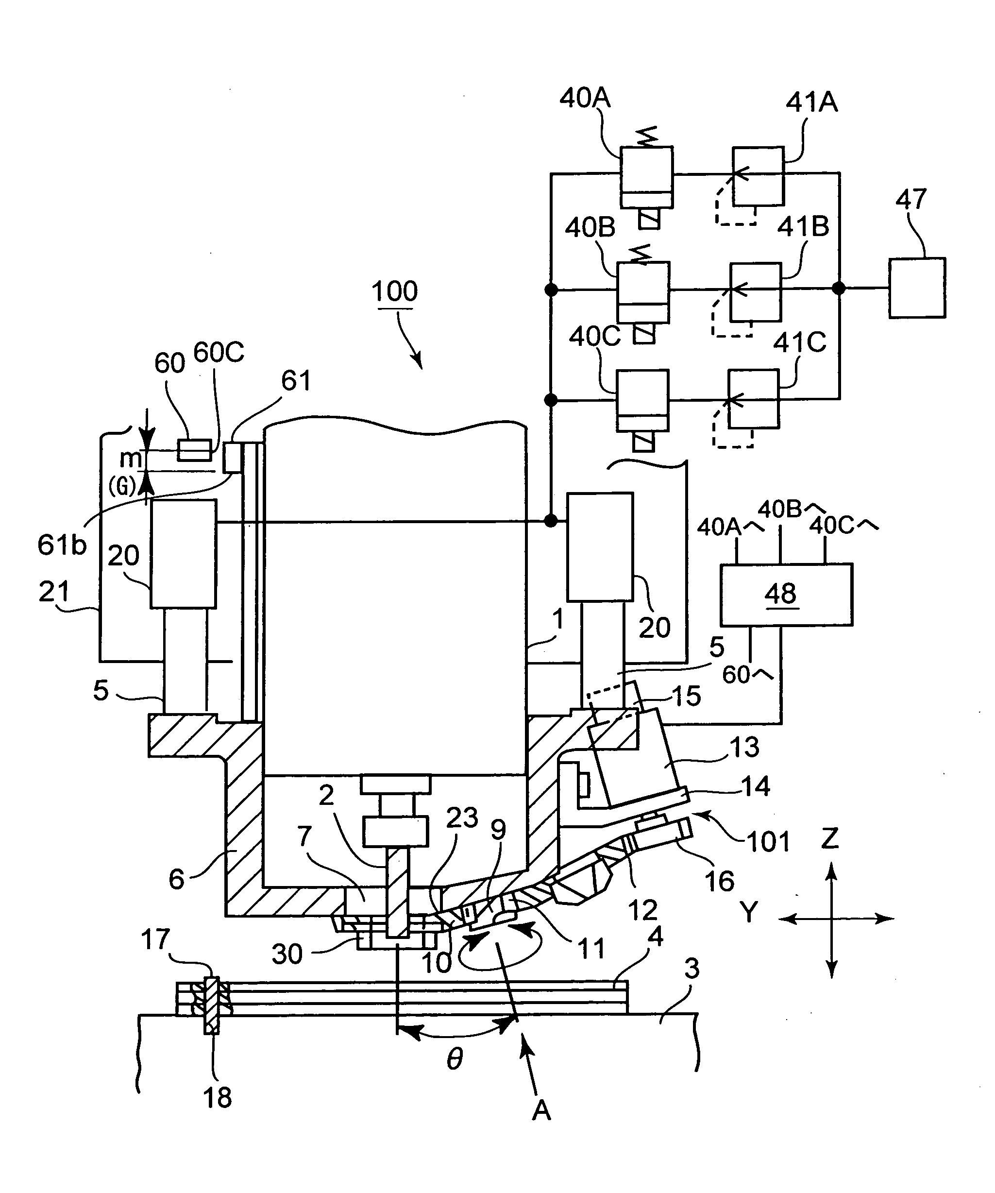
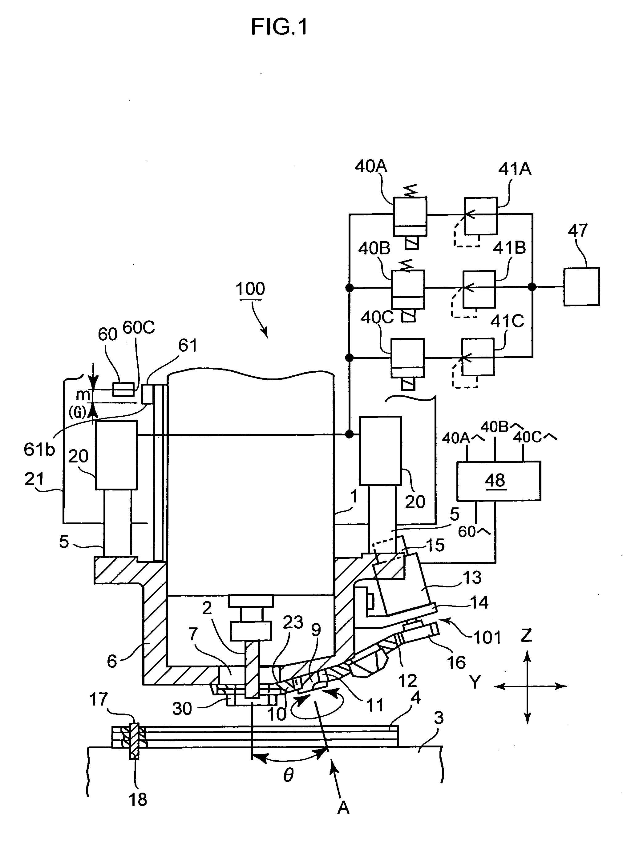
[0019]FIG. 1 is a schematic front section view of the printed circuit board machining apparatus according to an embodiment of the invention, FIG. 2 is a view of FIG. 1 seen from an arrow A and FIGS. 3A, 3B and 3C are diagrams for explaining an operation of a pressure piece of the printed circuit board machining apparatus of the invention.

[0020]The printed circuit board machining apparatus 100 is arranged so as to be able to machine grooves, profiles and holes on a workpiece 4. It is noted that an under plate is always disposed under the workpiece to prevent a table for mounting the workpiece from being damaged in machining the grooves, profiles and holes.

[0021]The printed circuit board machining apparatus 100 holds a tool 2 removably by a cylindrical spindle 1. The spindle 1 is fixed to a Z-table 21. The Z-table 21 is supported movably in a vertical direction (in a direct...


PUM

PropertyMeasurementUnit
diameteraaaaaaaaaa
diameteraaaaaaaaaa
pressureaaaaaaaaaa

Abstract

A printed circuit board machining apparatus includes a spindle that holds a tool for machining a printed circuit board and a pressure unit for pressing the printed circuit board to a table in machining the printed circuit board. The pressure unit includes a pressure foot movable up an down along the spindle, a rotating member having a plurality of pressure pieces through which a through hole for passing the tool is formed and provided so as to select one among the plurality of pressure pieces, a motor for moving the rotating member, cylinders and electromagnetic valves for moving the pressure foot up and down and a control section for controlling the cylinders and electromagnetic valves. The control section rotates the motor so as to select the pressure piece and controls the cylinders and the electromagnetic valves to change force for pressing the printed circuit board.

Description

BACKGROUND OF THE INVENTION[0001]1. Field of the Invention[0002]The present invention relates to a printed circuit board machining apparatus.[0003]2. Description of Related Art[0004]Hithertofore, a tool (drill) has been used in general to drill holes on a printed circuit board (referred to as a “workpiece” hereinafter) by a printed circuit board machining apparatus. Although the tool receives pressing force in a direction along an axial line of the tool in this case, it barely receives force in a direction intersecting with the axial line. Therefore, the printed circuit board machining apparatus can drill holes of small diameter (e.g., about 0.1 mm) at high speed without enhancing rigidity of the tool in the direction intersecting with the axial line of the tool.[0005]However, there is a case when burr is generated around the machined holes. Then, a countermeasure is taken so as to prevent the burr from being generated by placing an upper plate on an upper side of the workpiece and ...

Claims


Application Information

Patent Timeline
Patent Type & Authority Applications(United States)
IPC IPC(8): B23B47/00
CPCH05K3/0047H05K2203/0278Y10T408/56253Y10T408/56245Y10T408/50H05K13/00H05K13/02B30B15/06
Inventor KADO, HIROFUMIKAMATA, HIROYUKITAKAHASHI, SHINTARONAGASAWA, KATSUHIRO
Owner HITACHI SEIKO LTD
Why Eureka
Try Eureka