Centrifugal air compressor

a centrifugal air compressor and centrifugal technology, applied in the direction of non-positive displacement fluid engines, pump control, pump components, etc., can solve the problems of significant deformation of the start performance of centrifugal air compressors, and achieve the effect of stably starting and eliminating the adhesion of rotary vanes

Inactive Publication Date: 2008-11-27
JTEKT CORP
View PDF7 Cites 14 Cited by
  • Summary
  • Abstract
  • Description
  • Claims
  • Application Information

AI Technical Summary

Benefits of technology

[0007]An objective of the present invention is to provide a centrifugal air compressor that eliminates adhesion of a rotary vane due to a congelation, thereby allowing the rotary vane to be stably started.

Problems solved by technology

In the case where adhesion of a rotary vane cannot be reliably eliminated, the starting performance of the centrifugal air compressors is significantly degraded.

Method used


Image

  • Centrifugal air compressor
  • Centrifugal air compressor
  • Centrifugal air compressor

Examples


Embodiment Construction

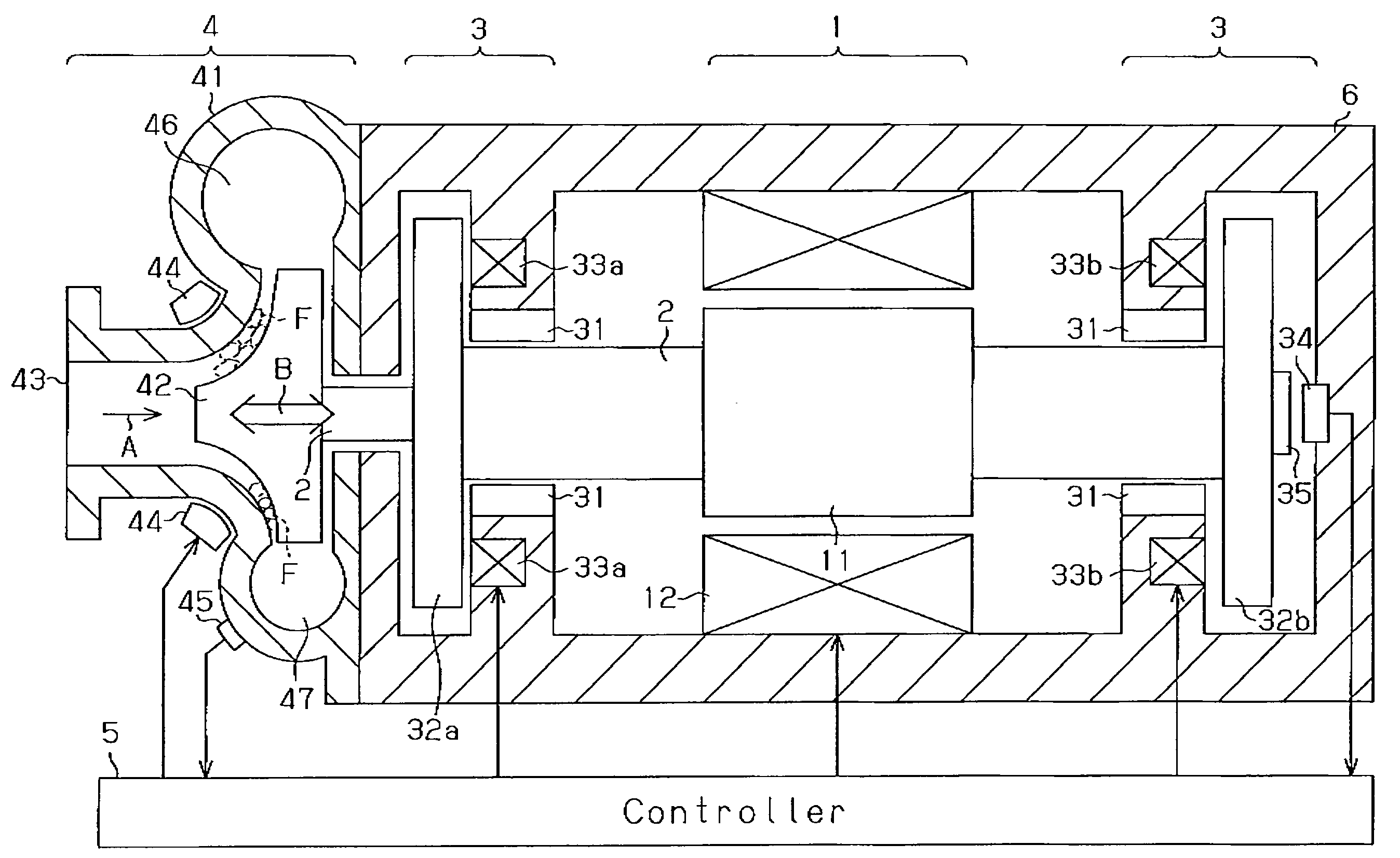
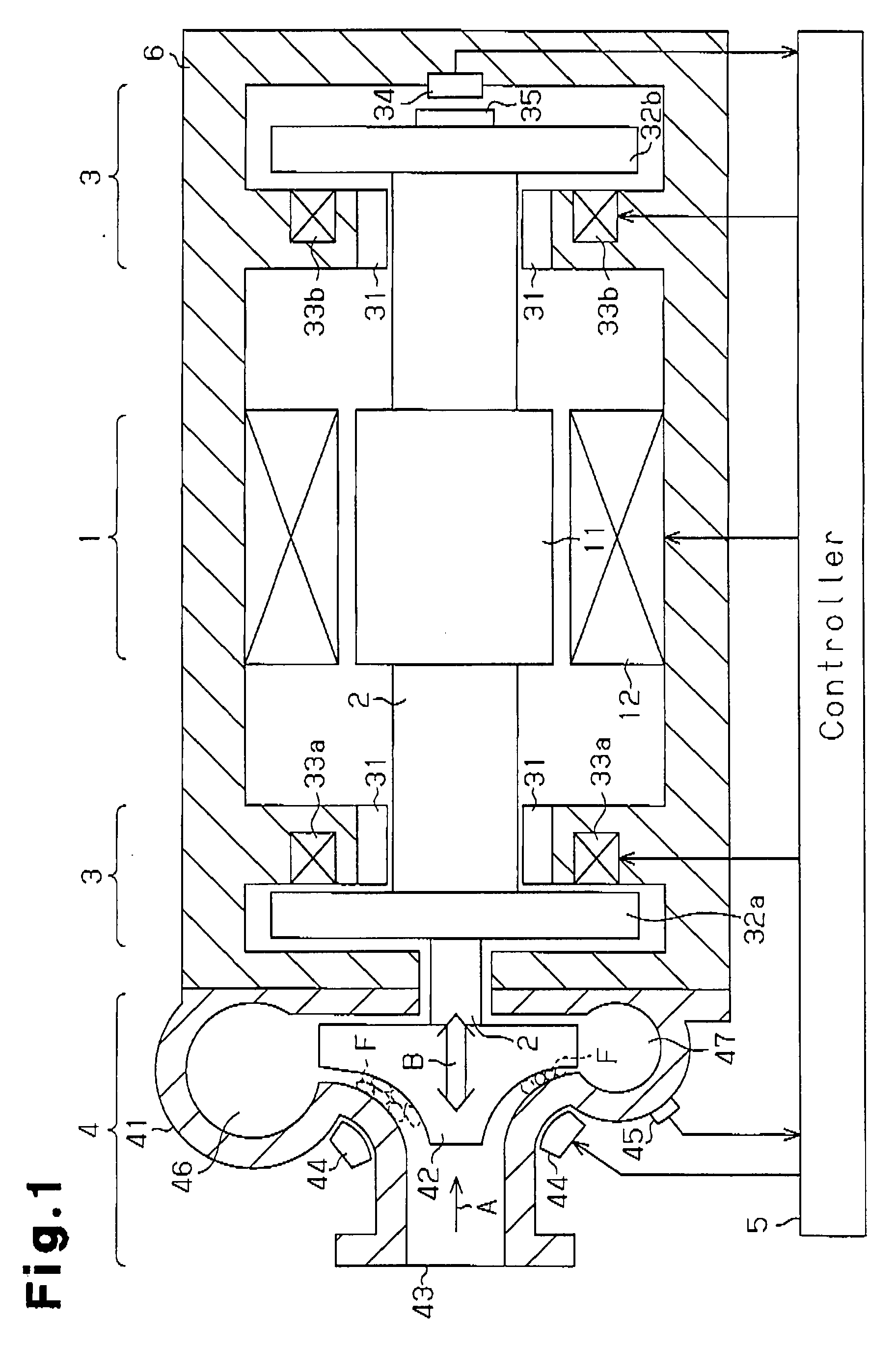
[0011]A centrifugal air compressor according to one embodiment of the present invention will now be described with reference to FIGS. 1 and 2.

[0012]As shown in FIG. 1, the centrifugal air compressor of the present embodiment is provided with a motor 1 accommodated in a housing 6, a rotary shaft 2 rotated by the motor 1, bearing devices 3 for supporting the rotary shaft 2, a compressor portion 4, and a controller 5. The controller 5 is composed of a microcomputer or a DSP (digital signal processor), and a driving circuit, and controls the overall operation of the compressor. Hereinafter, a detailed explanation will be made for the constitution and functions of each portion.

[0013]The motor 1 is provided with a rotor 11 fixed to the rotary shaft 2 and a stator 12 installed at the housing 6 so as to encompass the rotor 11. During normal operation, electricity is supplied to the stator 12 through the controller 5, thereby generating an electromagnetic force, The rotor 11 is rotated toget...


PUM


Abstract

If the ambient temperature of a pressure volute measured by a temperature sensor exceeds 0° C., a compressor is instantly started at normal operation. If the temperature of the pressure volute measured by the temperature sensor is 0° C. or lower, there is a possibility that a rotary vane may be adhered to the pressure volute due to a congelation. Therefore, vibration along the axial direction is given to the rotary shaft by way of an axial magnetic bearing. If the vibration amplitude of the thus given vibration exceeds a predetermined value, the compressor is started at normal operation after idle operation. On the other hand, if the vibration amplitude is lower than a predetermined value, it is determined that the thus given vibration is unable to eliminate the adhesion of the rotary vane due to the congelation, and the heater is actuated to heat the pressure volute only for a predetermined time. Thereafter, the ambient temperature is detected again, and if the ambient temperature exceeds 0° C., the compressor is started,

Description

[0001]This application is based on and claims priority from Japanese Patent Application No. 2007-044528 filed on Feb. 23, 2007, the entire contents of which are incorporated herein by reference.BACKGROUND OF THE INVENTION[0002]The present invention relates to a centrifugal air compressor, which is provided with a rotary shaft supported by a magnetic bearing and a rotary vane that is encompassed by a pressure volute while being connected to the rotary shaft.[0003]As is well known, centrifugal air compressors are structured so as to compress intake air by rotating rotary vanes. Therefore, a rotary shaft for rotating the rotary vanes must be supported by a structure capable of withstanding high-speed rotation. Many of the thus structured centrifugal air compressors adopt a magnetic bearing capable of supporting the rotary shaft in a non-contact manner as a bearing system for supporting the rotary shaft.[0004]Some of these compressors are used outdoors, for example, as on-vehicle compre...

Claims


Application Information

Patent Timeline
Patent Type & Authority Applications(United States)
IPC IPC(8): F04D27/00F04D29/058
CPCF04D27/001F04D27/0276F04D29/058F04D29/584F04D27/0292F04D29/051F04D29/057
Inventor TANIGUCHI, MANABUUEYAMA, HIROCHIKAMIYAGAWA, YASUKATA
Owner JTEKT CORP
Why Eureka
Try Eureka