Lightweight moulded piece and corresponding production method

a technology of light weight and moulded parts, which is applied in the field of lightweight moulded parts, can solve the problems of conventional lightweight moulded parts, and sandwich structures with a light honeycomb core, and achieves high shear force flexural load, high shear force load, and high energy absorption of disclosed sandwich elements

Inactive Publication Date: 2010-06-10
FACHHOCHSCHULE LANDSHUT
View PDF6 Cites 9 Cited by
  • Summary
  • Abstract
  • Description
  • Claims
  • Application Information

AI Technical Summary

Benefits of technology

[0017]The disclosed sandwich elements are advantageously used in lightweight constructions which support a shear force flexural load. These may for example be flooring or cargo bay flooring in aircraft, buses, boats, ships or automobiles. In vans or pickup trucks, the loading platforms and driving cab rear walls may advantageously be formed with the disclosed sandwich construction. In the field of construction, the disclosed sandwich elements may be used for double floors (upper floors for example in computer rooms) or as lightweight partition walls, lightweight cover elements, or doors and gates. In aircraft construction or shipbuilding, partitions (for example pressure domes) may be produced in the form of a sandwich element with the disclosed construction. In automotive engineering, the disclosed sandwich construction may for example be used in the undercarriage as the floor of the boot or for the backrest of the back row of seats. The backrest for the back seats may be divided (for example one third to two thirds), which causes a very high shear force fle...

Problems solved by technology

Conventional lightweight moulded parts, such as sandwich structures with a light honeycomb core, generally cannot be produced curved.
This is a disadvantage for sandwich constructions, which are generally subjected to shear force.
The backrest for the back seats may be divided (for exampl...

Method used


Image

  • Lightweight moulded piece and corresponding production method
  • Lightweight moulded piece and corresponding production method
  • Lightweight moulded piece and corresponding production method

Examples


first embodiment

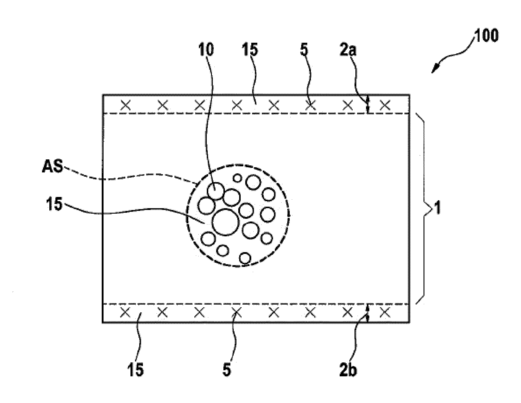
[0034]FIG. 1 is a schematic cross-sectional view of a lightweight moulded part according to the present invention.

[0035]In FIG. 1, reference numeral 100 denotes a lightweight moulded part made of a lightweight composite material 10, 15 which comprises a matrix material 15 and a filler material 10. In the present example, the filler material 10 consists for example of hollow spheres or foam granules with a diameter of between 4 mm and 6 mm, whereas the matrix material is a cured polyamide-based plastics material. To simplify the drawing, FIG. 1 only shows a portion AS, enclosed by a dashed line, of the core region 1. Moreover, the lightweight moulded part 100 comprises a first upper surface cover layer region 2a and a second lower surface cover layer region 2b, each of which comprises a fibre material 5 which is integrated into the matrix material 15 of the core region. In this case, the dashed line in FIG. 1 represents a virtual boundary of the core region up to which the filler mat...

second embodiment

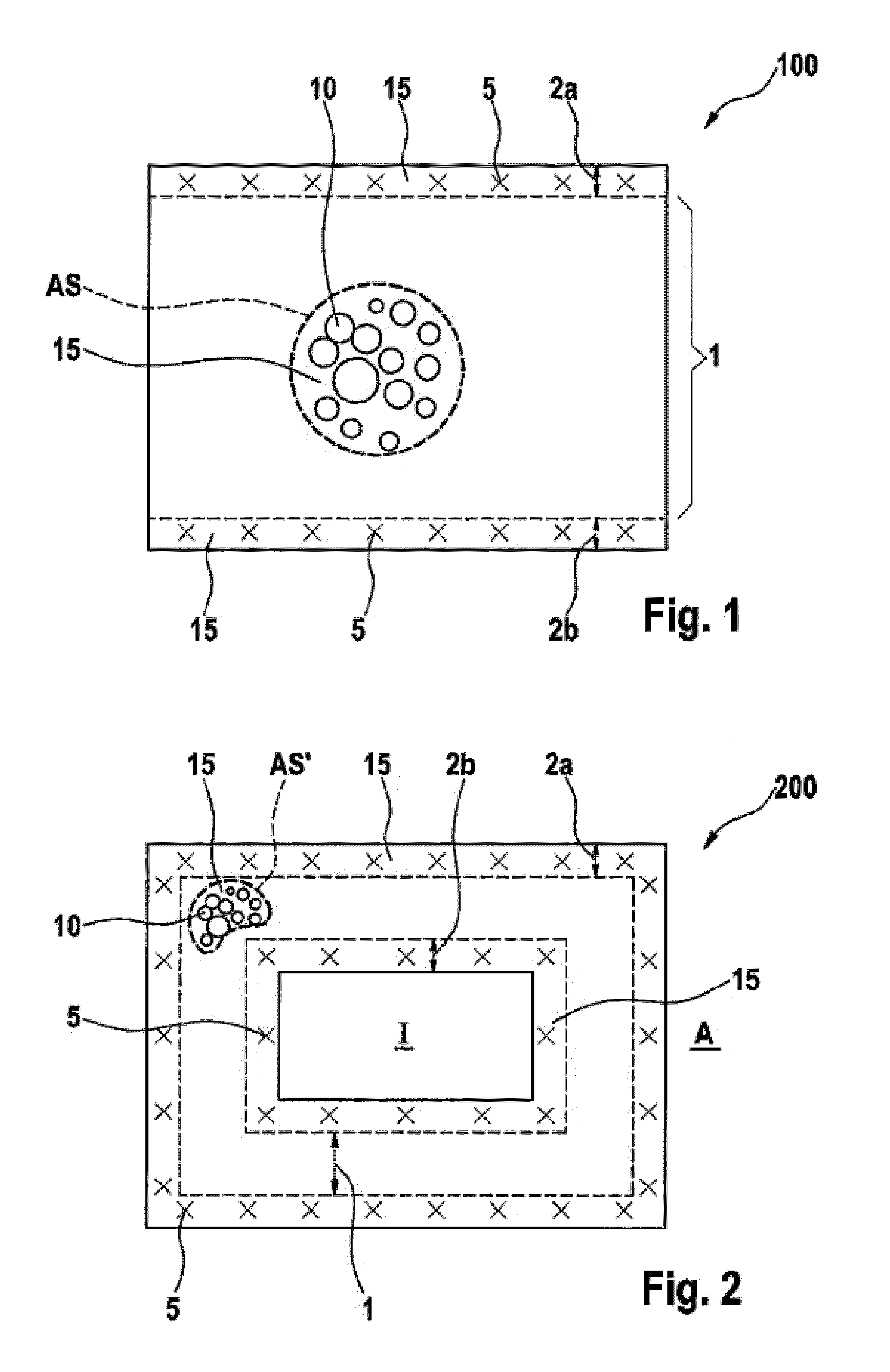
[0038]FIG. 2 is a schematic cross-sectional view of a lightweight moulded part in the form of a hollow profile according to the present invention.

[0039]The lightweight moulded part 200 according to FIG. 2 is in the form of a hollow profile, i.e. a tubular configuration, the reference A denoting an exterior and the reference I denoting an interior of the tube. In this embodiment, an external fibre-reinforced cover layer region 2a is provided as a boundary for the exterior A and an internal fibre-reinforced cover layer region 2b is provided as a boundary for the interior I. The core region 1 corresponds, as is shown in the detail AS′, to the core region of the lightweight moulded part in FIG. 1.

[0040]A single surface cover layer region 2a or 2b or further additional end face cover layer regions would of course also be possible.

third embodiment

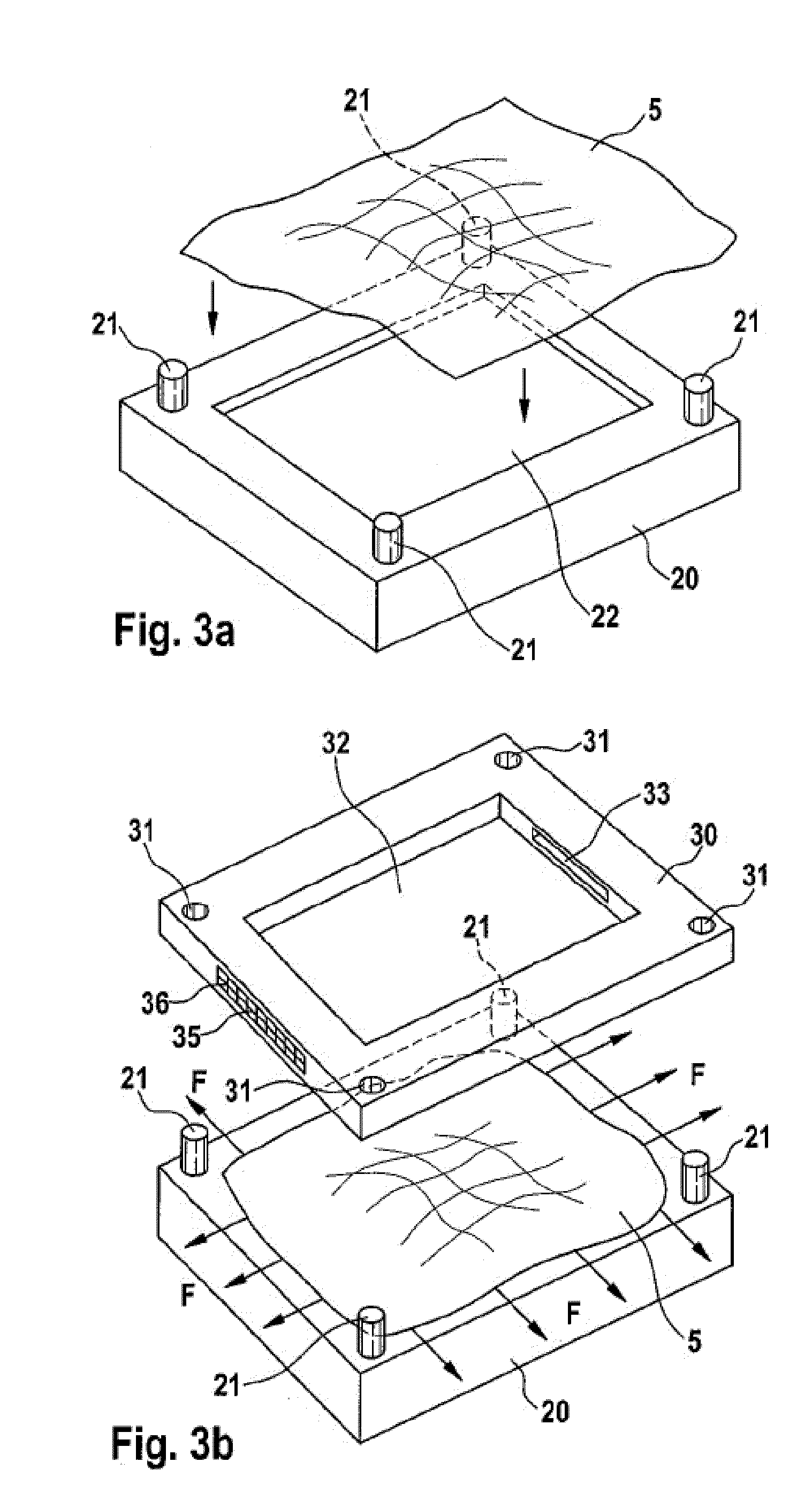
[0041]FIGS. 3a)-d) are schematic perspective views illustrating a production method for a lightweight moulded part according to the present invention;

[0042]In FIG. 3a), reference numeral 20 denotes a mould part in the form of a mould lid with a central recess 22 and alignment pins 21. In a first process step, the required layer or layers of fibre material 5 (for example non-woven materials, bands, knitted materials, knitted fabrics, bonded materials or woven materials made of carbon, glass, aramid or metal fibres or other fibres) for a first cover layer region are applied to a horizontally positioned mould part 20, the layer or layers of the fibre material 5 being tightened over the recess 22. The recess 22 typically has a constant depth of 0.1 to 0.5 mm so as to allow good covering of the layer of fibre material 5 with the matrix material which is to be introduced later.

[0043]Continuing with reference to FIG. 3b), the layer or layers of fibre material 5 are tightened in the directi...


PUM

PropertyMeasurementUnit
Fractionaaaaaaaaaa
Fractionaaaaaaaaaa
Fractionaaaaaaaaaa

Abstract

The present invention provides a lightweight moulded part and a corresponding production method. The lightweight moulded part comprises a core region (1) made of a lightweight composite material (10, 15) which comprises a matrix material (15) and at least one filler material (10); at least one surface or near-surface cover layer region (2a, 2b) which comprises at least one layer of fibre material (5) and the matrix material (15); the layer (or layers) of fibre material (5) of the cover layer region (2a, 2b) being integrated into the matrix material (15) of the core region (1).

Description

PRIOR ART[0001]The present invention relates to a lightweight moulded part and a corresponding production method.[0002]Lightweight materials and moulded parts are nowadays used in many technical fields, such as automotive engineering, aircraft construction and shipbuilding, and in transport in general. They are distinguished by their high rigidity, strength and energy absorption capacity as well as a low density by comparison with conventional construction materials, and allow economical production of highly loaded construction elements. Lightweight materials with a density below 1.0 kg / dm3, and of which the density lies below that of most current plastics materials, are of particular interest.[0003]Conventional lightweight moulded parts, such as sandwich structures with a light honeycomb core, generally cannot be produced curved. It is generally only possible to produce sandwich elements with a single curve when using sandwich cores which are produced by folding paper or metal (thi...

Claims


Application Information

Patent Timeline
IPC IPC(8): B32B3/26
CPCB22F7/002B32B5/18B32B5/22C22C49/14B32B27/20C08K7/02C22C1/08B32B5/26Y10T428/249953Y10T428/249974B32B1/08B32B3/20C04B35/00
Inventor HUBER, OTTOKLAUS, HUBERT
Owner FACHHOCHSCHULE LANDSHUT
Why Eureka
Try Eureka