
Differential-pressure flow meter and flow-rate controller

a flow rate controller and flow meter technology, applied in the direction of volume metering, process and machine control, instruments, etc., can solve the problems of wasting time and effort, erroneous difference in measured flow rate, and requiring disassembly and cleaning treatment. , to achieve the effect of easy elimination

Active Publication Date: 2010-01-14
SURPASS IND
View PDF11 Cites 7 Cited by
  • Summary
  • Abstract
  • Description
  • Claims
  • Application Information

AI Technical Summary

Benefits of technology

[0010]Because of the above backgrounds, a differential-pressure flow meter and a flow-rate controller with use of an orifice are desirably configured to be capable of easily eliminating
[0011]adhesion to the orifice of an extraneous material such as a solid substance so as to start accurate measurement and control of a flow rate.
[0012]In view of the above circumstances, it is an object of the present invention to provide a differential-pressure flow meter and a flow-rate controller configured to be capable of, even in a case where an extraneous material such as a solid substance adheres to an orifice, easily eliminating such adhesion of the extraneous material such as the solid substance.

Problems solved by technology

Such adhesion of the solid substance causes an erroneous difference in measured flow rate.
However, the solid substance generated from the chemical solution or the like adheres so strongly that it often remains unremoved by such an ordinary cleaning treatment.
It is pointed out that such a disassembling treatment and a reverse cleaning treatment require much time and effort.
Furthermore, the reverse cleaning treatment of flowing a fluid cleaner in the direction opposite to the normal direction is impractical since the fluid cleaner flows in the direction opposite to the normally expected flow directon also in adjacent devices, resulting in unexpected troubles.

Method used


Image

  • Differential-pressure flow meter and flow-rate controller
  • Differential-pressure flow meter and flow-rate controller
  • Differential-pressure flow meter and flow-rate controller

Examples


Embodiment Construction

[0027]Below described with reference to the drawings are a differential-pressure flow meter and a flow-rate controller according to an embodiment of the present invention.

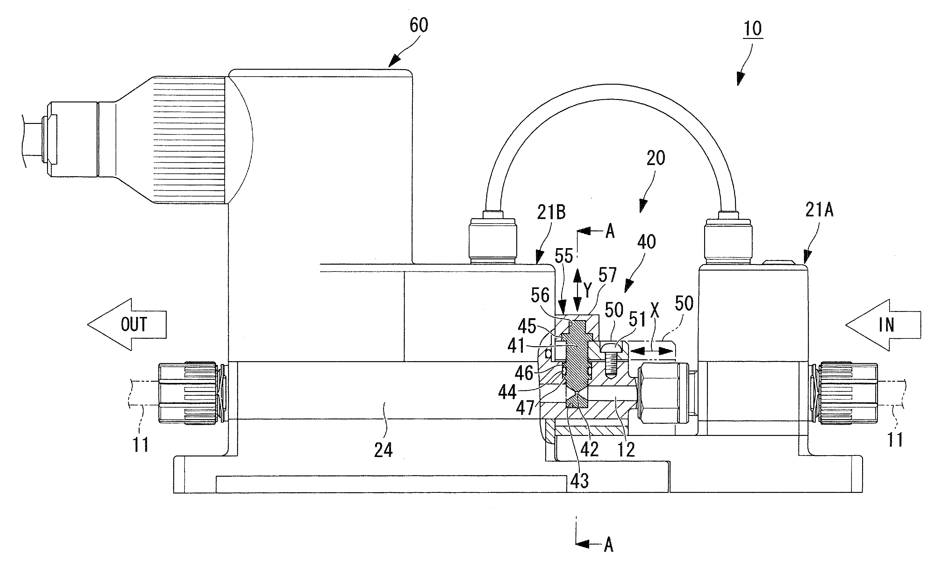
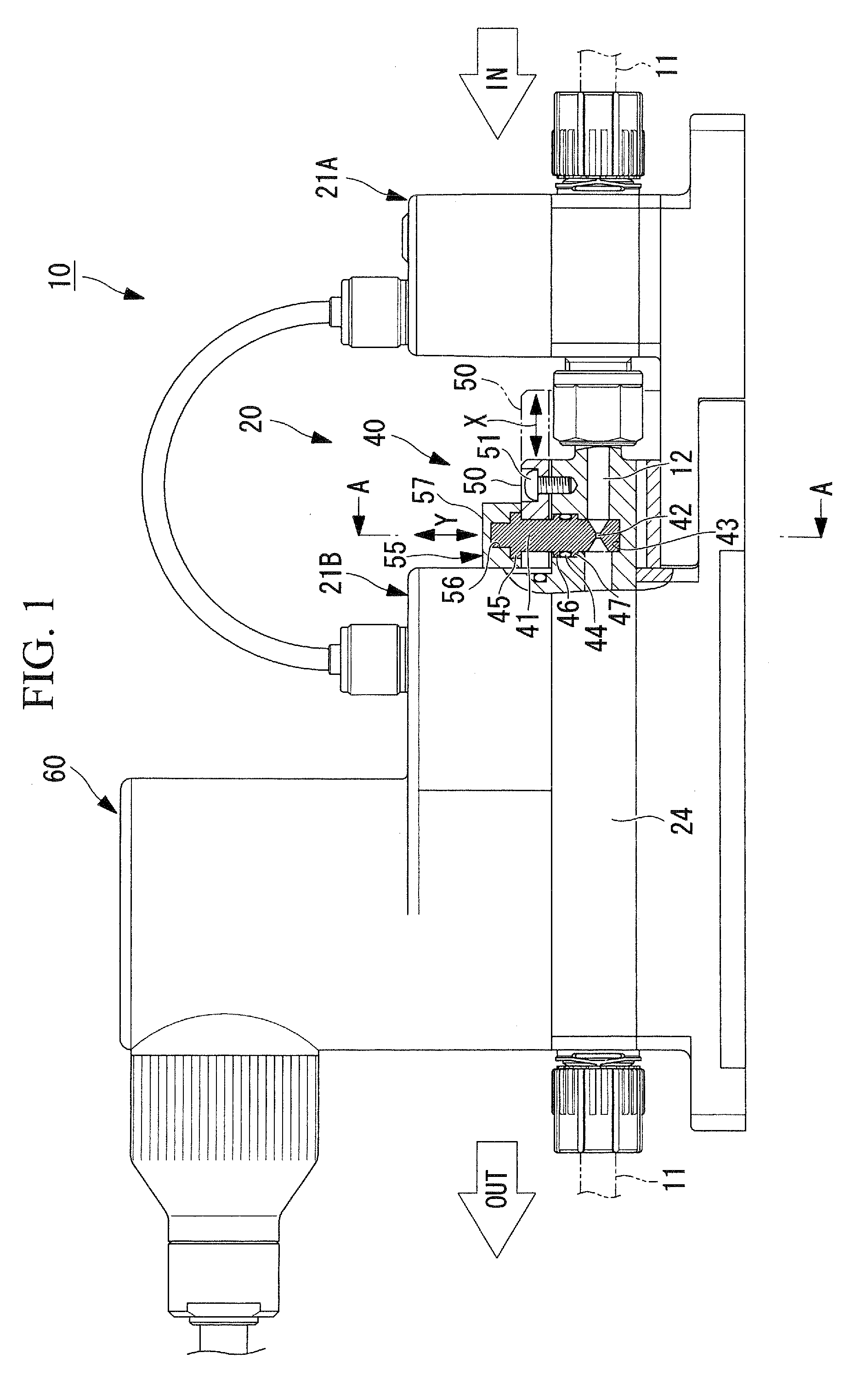
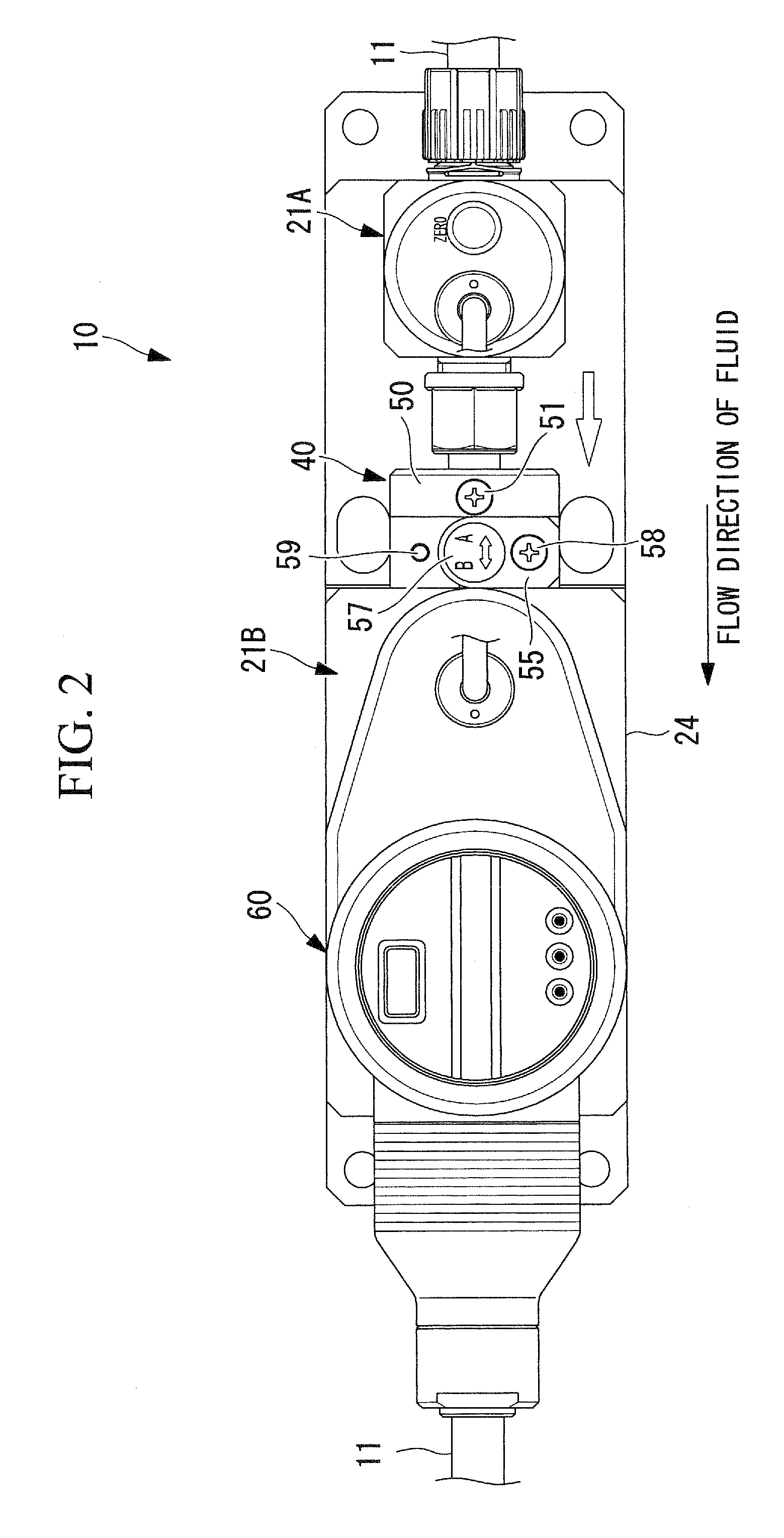
[0028]In the embodiment shown in FIGS. 1 to 5, FIG. 1 is a front view of a flow-rate controller 10 with a main portion thereof being shown in cross-section, FIG. 2 is a plan view of the flow-rate controller 10 shown in FIG. 1, and FIG. 3 is a vertical cross-sectional view (cut along line A-A in FIG. 1) of an orifice unit in FIG. 1. The flow-rate controller 10 is incorporated in a pipe 11 that is communicated with a main fluid channel 12 to be described later, and controls to constantly maintain a flow rate of a fluid (such as a chemical solution) flowing in the fluid channel. The flow-rate controller 10 includes a differential-pressure flow meter 20 that measures an actual flow rate of a fluid, and a flow control valve 60 that allows an opening of a valve to be controlled. The differential-pressure flow meter 20 is...


PUM


Abstract

A differential-pressure flow meter is capable of easily eliminating adhesion to an orifice of an extraneous material. The differential-pressure flow meter includes: a pair of pressure sensors provided on a straight pipe part of a main fluid channel; an orifice unit interposed between the pair of pressure sensors; a columnar orifice body provided on the main fluid channel to be detachable in a direction orthogonal to a flow direction of a fluid in the main fluid channel; and an orifice hole penetrating the orifice body in the flow direction of the fluid, wherein the orifice body is rotatable at a prescribed installation position to reverse an upstream side and a downstream side with respect to the orifice hole, and flow rate measurement is performed by converting into a flow rate a difference in pressure that is obtained from two pressure values sensed respectively by the pair of pressure sensors.

Description

BACKGROUND OF THE INVENTION[0001]1. Field of the Invention[0002]The present invention relates to a differential-pressure flow meter and a flow-rate controller for use in a fluid transport pipe in various industrial fields including chemical plants, semiconductor manufacturing, foods, and biotechnology.[0003]This application is based on Japanese Patent Application No. 2008-178050, the content of which is incorporated herein by reference.[0004]2. Description of Related Art[0005]There is a differential-pressure flow meter conventionally and widely used for measuring a flow rate of a fluid. Such a differential-pressure flow meter includes pressure sensors in front of as well as in the rear of an orifice, and is used at a position to measure a pressure of a fluid containing a corrosive chemical such as nitric acid, hydrochloric acid, and hydrofluoric acid, of high purity, as in a semiconductor manufacturing process. Specifically, there is used a chemical solution containing hydrofluoric ...

Claims


Application Information

Patent Timeline
Patent Type & Authority Applications(United States)
IPC IPC(8): G01F1/42
CPCG01F1/42G05D7/0635G01F15/12Y10T137/7761G01F1/34
Inventor IGARASHI, HIROKI
Owner SURPASS IND
Learn More