Implant drill

a technology for implants and drills, applied in dental tools, dental surgery, medical science, etc., can solve the problems of difficult implant placement, difficult implant operation, and dentists' unwillingness to perform implant operation in these patients, and achieve the effect of easy and simple boring of the maxillary bone and easy operation of the maxillary sinus lifting

a technology for implants and drills, applied in dental tools, dental surgery, medical science, etc., can solve the problems of difficult implant placement, difficult implant operation, and dentists' unwillingness to perform implant operation in these patients, and achieve the effect of easy and simple boring of the maxillary bone and easy operation of the maxillary sinus lifting

US20080293010A1Inactive Publication Date: 2008-11-27SAHAVIRIYA STEEL INDUSTRIES

Image

  • Implant drill
  • Implant drill
  • Implant drill

Examples


Embodiment Construction

[0028]The present invention will now be described more fully hereinafter with reference to the accompanying drawings, in which preferred exemplary embodiments of the invention are shown.

[0029]FIGS. 3 through 7 are views for explaining an implant drill for maxillary sinus lifting according to an exemplary embodiment of the present invention.

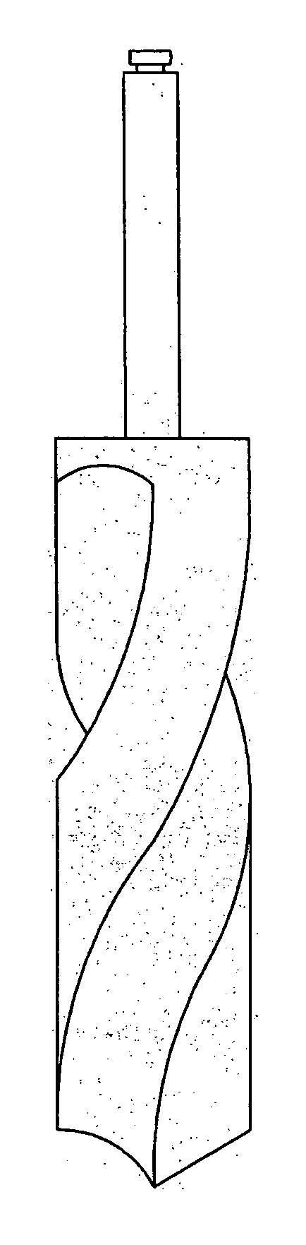
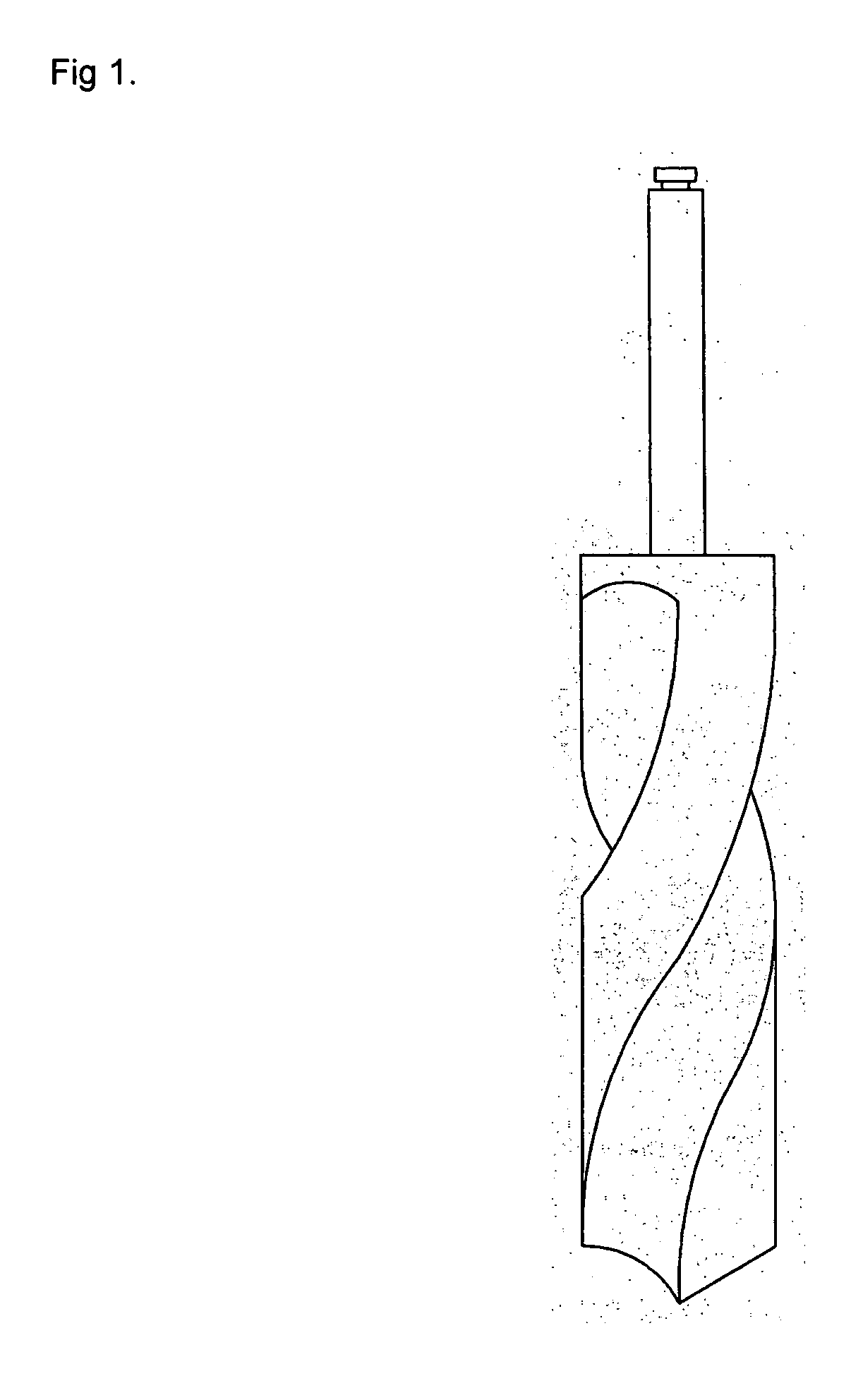
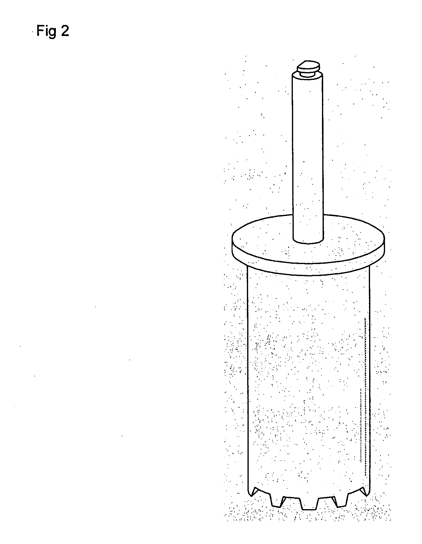
[0030]As illustrated in FIG. 3, the implant drill comprises a connector 1 and a drill bit 2 wherein a through-aperture 3 formed at the center part of the drill bit 2 in a vertical direction and a lifter is equipped in the through-aperture.

[0031]The connector 1 is mounted onto a general dental hand piece (not shown in the figure).

[0032]As shown in the FIG. 3, it is prefer that the lifter is a fluid pressure apparatus which let fluid flow out through the through-aperture. The fluid pressure apparatus includes a presser (not shown in the figure) and a path 31 to the through-aperture 3. The fluid pressure apparatus includes hydraulic lifter.

[0033]As s...


PUM


Abstract

There is provided an implant drill for maxillary sinus lifting, which is capable of easily and simply boring the maxillary bone, without damaging the lining membrane of the maxillary sinus, to easily operate the maxillary sinus lifting and to expand a boring part of the maxillary born for implant placement. The implant drill for maxillary sinus lifting, which includes a central shaft with a shank in a body to be mounted onto a general dental hand piece, comprises a protrusion member elastically positioned in the body so as to move forward and backward or a lifting member being free from the rotation of the body.

Description

[0001]The present application is a Continuation In Part application of the PCT / KR2007 / 000486 (WO 2007 / 094574 A1) filed 26 Jan. 2007.TECHNICAL FIELD[0002]The present invention relates to a dental implant drill, and more particularly, to an implant drill for maxillary sinus lifting, which is capable of easily and simply boring the maxillary bone, without damaging the lining membrane of the maxillary sinus, to easily operate the maxillary sinus lifting and to expand a boring part of the maxillary bone for implant placement.BACKGROUND ART[0003]Today, the implant operation for placing an artificial tooth has been rapidly spread.[0004]However, quite a number of patients have the mouth structures with difficult in performing the implant operation. Some dentists are reluctant to perform the implant operation in these patients.[0005]Specifically, when a remaining bone in a posterior region where the maxillary sinus is positioned is insufficient, it is very hard to place an implant. In this c...

Claims


Application Information

Patent Timeline
27 Nov 2008
Publication
US20080293010A1
IPC
A61C3/02
CPC
A61C8/0089; A61C8/0092
Inventors
SONG, YOUNG WAN