Direction and distance correcting golf putter

a golf putter and distance correction technology, applied in the direction of golf clubs, racket sports, sport apparatus, etc., can solve the problems of repeated technique, exquisitely difficult task, and inability to achieve the same result, so as to reduce the magnitude of errors and achieve a larger degree of forgiveness

Inactive Publication Date: 2008-11-27
BITKO DAVID M +3
View PDF38 Cites 10 Cited by
  • Summary
  • Abstract
  • Description
  • Claims
  • Application Information

AI Technical Summary

Benefits of technology

[0005]The design intent of the putter of the present invention is to provide both passive and active design enhancement elements. As previously mentioned, passive improvements reduce the magnitude of the errors introduced by mishit balls, while active enhancements are intended to correct such errors, providing a larger degree of forgiveness. Active enhancement is accomplished by the invention by the introduction of an actively compliant beam which makes use of energy stored in the beam when it is stressed during ball impact and which is released in a timely fashion, thus bringing the putter face back square to the putting line at the instant of ball and putter face separation. Passive enhancement takes the form of strategically placed visual alignment groove sight lines on the top surface or crown of the putter. This feature results in truer alignment with the intended putting line during set up.
[0006]More specifically, the golf putter of the present invention comprises a head of an esthetically appropriate shape combined with an actively compliant beam which is parallel to the face of the putter. The beam connects to a shaft at a suitable location along its length and is separated from the head except for its ends. The force of impact between the face of the putter and the ball on the putter face sweet spot causes a stress to develop in the beam, resulting in a deflection in the beam proportional to the force of the impact, while maintaining the putter face orientation with respect to the putting line. Impacts which miss the sweet spot will cause the putter face to skew to an angle with respect to the putting line, also introducing a proportional flexure of the beam, depending on the distance between the sweet spot and the point of impact. The beam has a characteristic time such that as the force between the ball and the putter face decreases to zero after impact, the beam flexure simultaneously recovers causing the putter face to return to its original putting line orientation at almost the same instant the ball leaves the putter face, thereby providing distance and directional correction for mishit putts. Additionally, when a putter head with a suitable moment of inertia is coupled with an actively compliant beam, feel via the sense of sound, touch and alignment are substantially enhanced.

Problems solved by technology

It is generally agreed that a repeatable technique is a prime and exquisitely difficult task to achieve, not only for tempo to control distance, but also to maintain putter face orientation to the intended putting line.
Every golfer has individual idiosyncrasies that can introduce variations in the swing path, face orientation and / or timing, so that the same result is not achieved even on repeated attempts to hole a putt of more than a few feet.

Method used


Image

  • Direction and distance correcting golf putter
  • Direction and distance correcting golf putter
  • Direction and distance correcting golf putter

Examples


Embodiment Construction

The Beam Putter

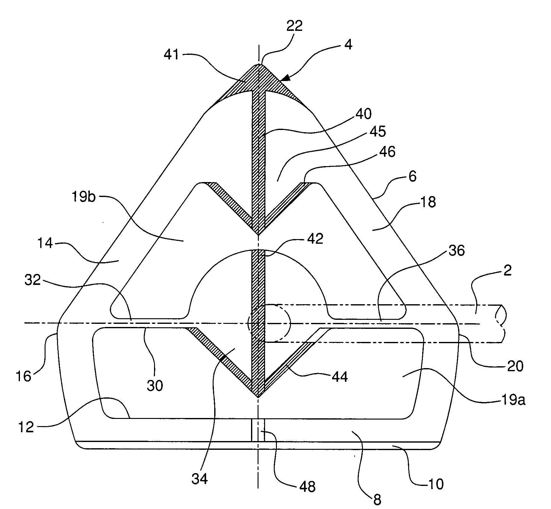
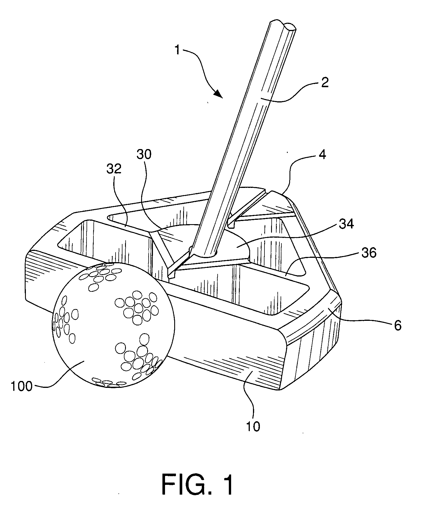
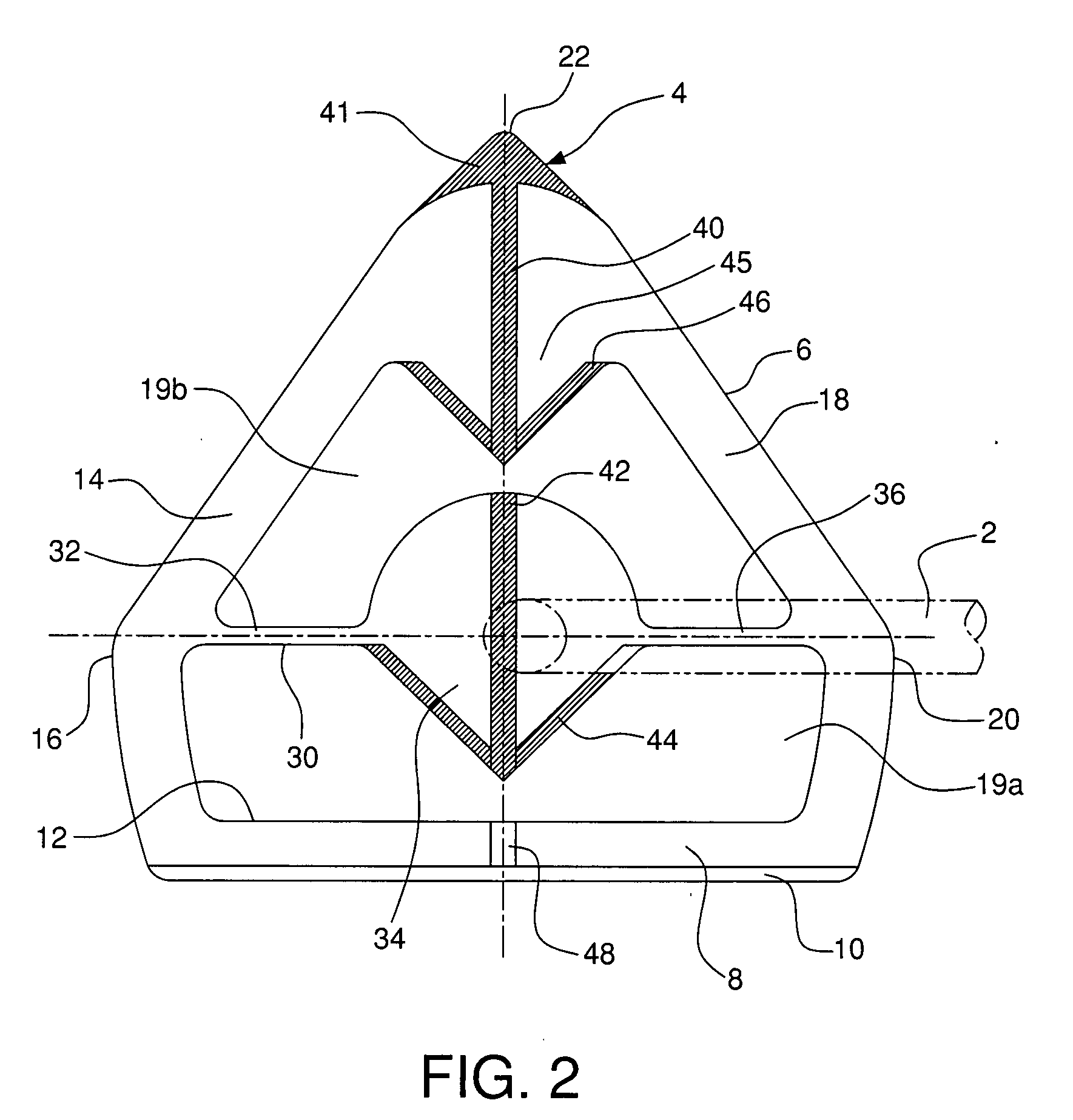
[0030]The preferred embodiment of the present invention, shown in FIGS. 1-4, comprises golf club 1 with golf shaft 2 and golf head 4. Head 4 can be provided with any number of different hosel designs and connections well-known in the industry and accepted by the USGA. While the shafts used on most standard putters fall in the 17-18 degree angle range, USGA requirements state that when a putter is soled to the putting surface in the normal manner, the shaft must have a tilt angle greater than 10 degrees from the vertical axis.

[0031]Head 4 of the present invention comprises unitary body 6 with transversely extending front member 8 having ball impact surface or face 10 and opposite back surface 12. As seen most clearly in FIG. 4, face 10 is offset at a slight angle 5, e.g. 4 degrees, from the vertical axis. Extending from member 8 are forward perimeter wall member 14 having forward section 16 and rear perimeter wall member 18 having rearward section 20. Wall members 14 a...


PUM


Abstract

A golf putter has a putter head with an actively compliant beam which is parallel to the face of the putter. The beam connects to a shaft along its length and is separated from the head except for its ends. The force of impact between the face of the putter and the ball on the putter face sweet spot causes a stress to develop in the beam, resulting in a deflection in the beam proportional to the force of the impact, while maintaining the putter face orientation with respect to the putting line. Impacts which miss the sweet spot will cause the putter face to skew to an angle with respect to the putting line, also introducing a proportional flexure of the beam, depending on the distance between the sweet spot and the point of impact. The beam has a characteristic time such that as the force between the ball and the putter face decreases to zero after impact, the beam flexure simultaneously recovers causing the putter face to return to its original putting line orientation at almost the same instant the ball leaves the putter face, thereby providing distance and directional correction for mishit putts. Additionally, when a putter head with a suitable moment of inertia is coupled with an actively compliant beam, feel and alignment are substantially enhanced. The putter also uses a unique visual alignment sight line groove on the top surface of the putter head, extending from the face to the back of the putter. The groove is perpendicular to the face of the putter and may have tapered side walls. It is positioned directly above and parallel to the center of mass and the sweet spot, so that it can be positioned directly over the intended putting line when the putter is properly located on the putting surface. The base of the groove has contrasting stripes, so that when the golfer's dominant eye is properly located over the groove, the entire stripped base of the groove is visible to the golfer.

Description

BACKGROUND OF THE INVENTION[0001]It is generally accepted that preparation for a putt begins with the ability of the golfer to read the character of the green (with regard to slope, speed, grain direction, ball break, etc.) so that a proper putting line can be selected. While somewhat intuitive for a few golfers, this ability is usually developed as a result of practical experience which enables a golfer to develop a useful technique. Even so, it is normal even for many professional golfers to call on the services of their caddy for help in selecting a putting line and a suggestion of required ball speed. This step is so important, many golfers make use of a largely discredited technique called plumb bobbing, i.e. using the putter's shaft as a vertical reference guide. Still, a patent designed in accordance with U.S. Pat. No. 6,358,162 has been found to be United States Golf Association (USGA) conforming. This design provides accurate horizontal and vertical references, and has prov...

Claims


Application Information

Patent Timeline
Patent Type & Authority Applications(United States)
IPC IPC(8): A63B53/04
CPCA63B53/0487A63B2053/0408A63B2053/0441A63B2053/0491A63B2069/3682A63B60/02A63B53/0408A63B53/0441A63B69/3682
Inventor BITKO, DAVID M.BITKO, SHELDON S.COON, ROBERT A.PIOTROWSKI, JOHN
Owner BITKO DAVID M
Why Eureka
Try Eureka