Device for Preventing Gear Hopout in a Tooth Clutch in a Vehicle Transmission

a technology of transmission and gear, which is applied in the direction of clutches, gearing control, gearing elements, etc., can solve the problems of insufficient self-retaining action of conventional back-tapered clutch teeth, the tendency to turn into an unstable state, and the inability to prevent relative motion, etc., to reduce the possibility of gear hopout, reduce production costs, and limit the effect of possible misalignment of the supported sha

Inactive Publication Date: 2008-11-27
VOLVO LASTVAGNAR AB
View PDF7 Cites 6 Cited by
  • Summary
  • Abstract
  • Description
  • Claims
  • Application Information

AI Technical Summary

Benefits of technology

[0001]The present invention relates to vehicle transmissions, and more particularly to a device for preventing gear hopout in tooth clutches that are subjected to misalignment due to forces acting on rotating parts they connect.
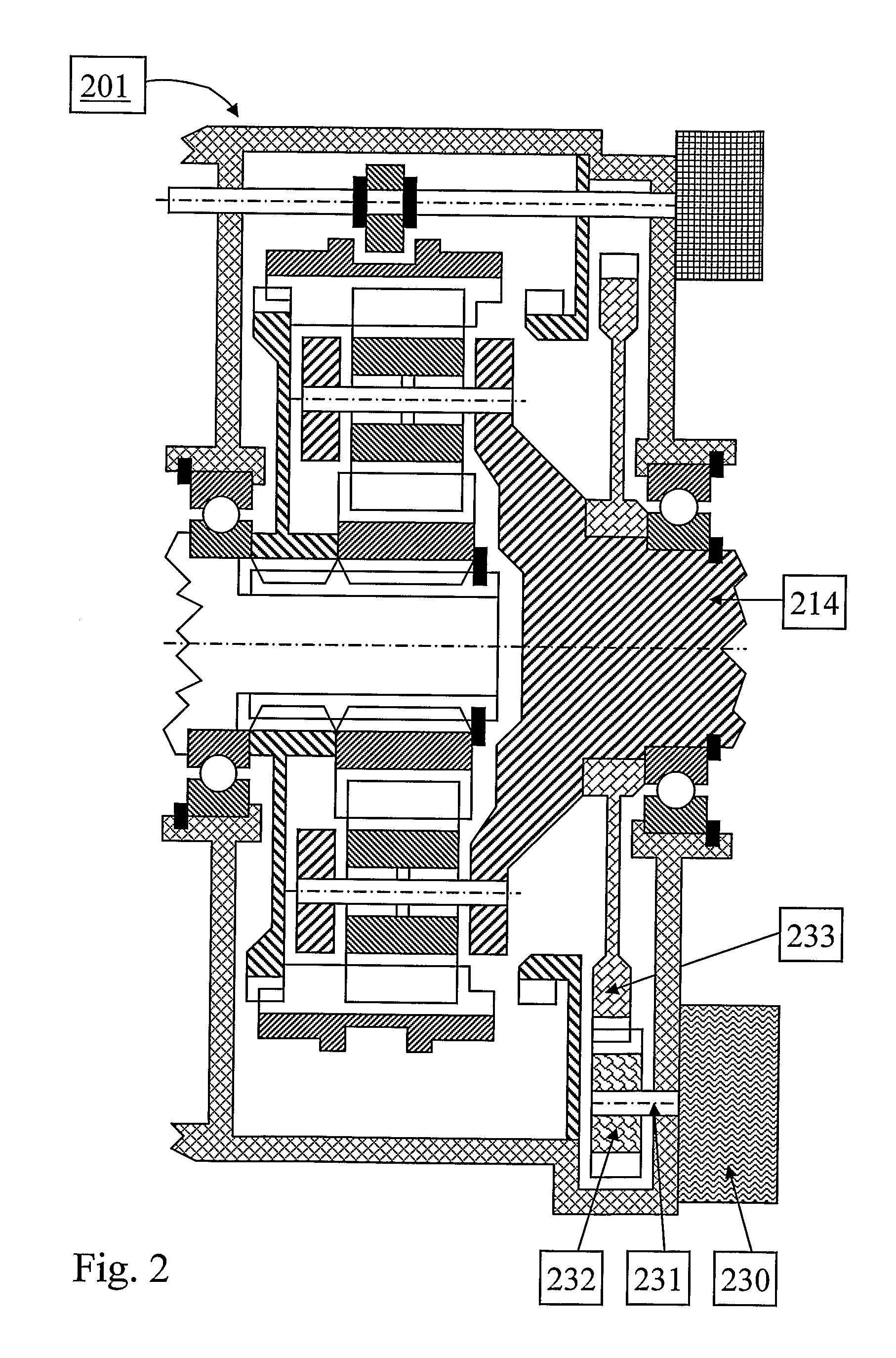
[0011]There are some applications where conventionally made back-tapered clutch teeth have been shown to have insufficient self-retaining action. One example is shown in FIG. 2, where, in comparison with FIG. 1a, a retarder unit 230 has been added to the range section 201. The retarder unit 230 is an auxiliary brake that can be used in long down-hill slopes in order to reduce wear and prevent over-heating of the ordinary wheel brakes of the vehicle. The retarder unit is driven by a retarder shaft 231 that is rotatably connected to a retarder driven gearwheel 232. In turn, the retarder driven gearwheel 232 meshes with a retarder driver gearwheel 233 that is rotationally connected to the output shaft 214 of the range section 201.
[0012]When the retarder unit 230 is in operation, gear mesh forces will act on the retarder driver gearwheel 233. These forces will tend to misalign the output shaft 214. Normally, engine braking is used simultaneously with retarder operation. Thereby, torque will be transferred by the range section, and there will be contact forces in the gear meshes and between the clutch teeth of the range section. These contact forces will urge the parts of the range section towards a substantially coaxial state, as was described earlier. Hence, the contact forces will counteract the tendency of the gear mesh forces on the retarder driver gearwheel 233 to misalign the output shaft 214.
[0019]There are some known solutions to prevent gear hopouts of the type described above. In general, radial support devices, such as bearings, have been introduced or improved in order to limit the possible misalignment of the supported shaft. In U.S. Pat. No. 5,839,319 a splitter unit similar to the one in FIG. 4 is shown. However, a headset / fourth gear 74 (corresponding to the second gearwheel 454 in FIG. 4) is not supported by a main shaft (corresponding to 455 in FIG. 4) but by a spindle 62 that is rigidly secured to an input shaft 42 (corresponding to 452 in FIG. 4). Thereby, a gear mesh force acting on the headset / fourth gear 74 will not cause any significant urge to misalign the main shaft. Hence, the tendency for gear hopout has been eliminated. However, the additional spindle will imply increased production cost.
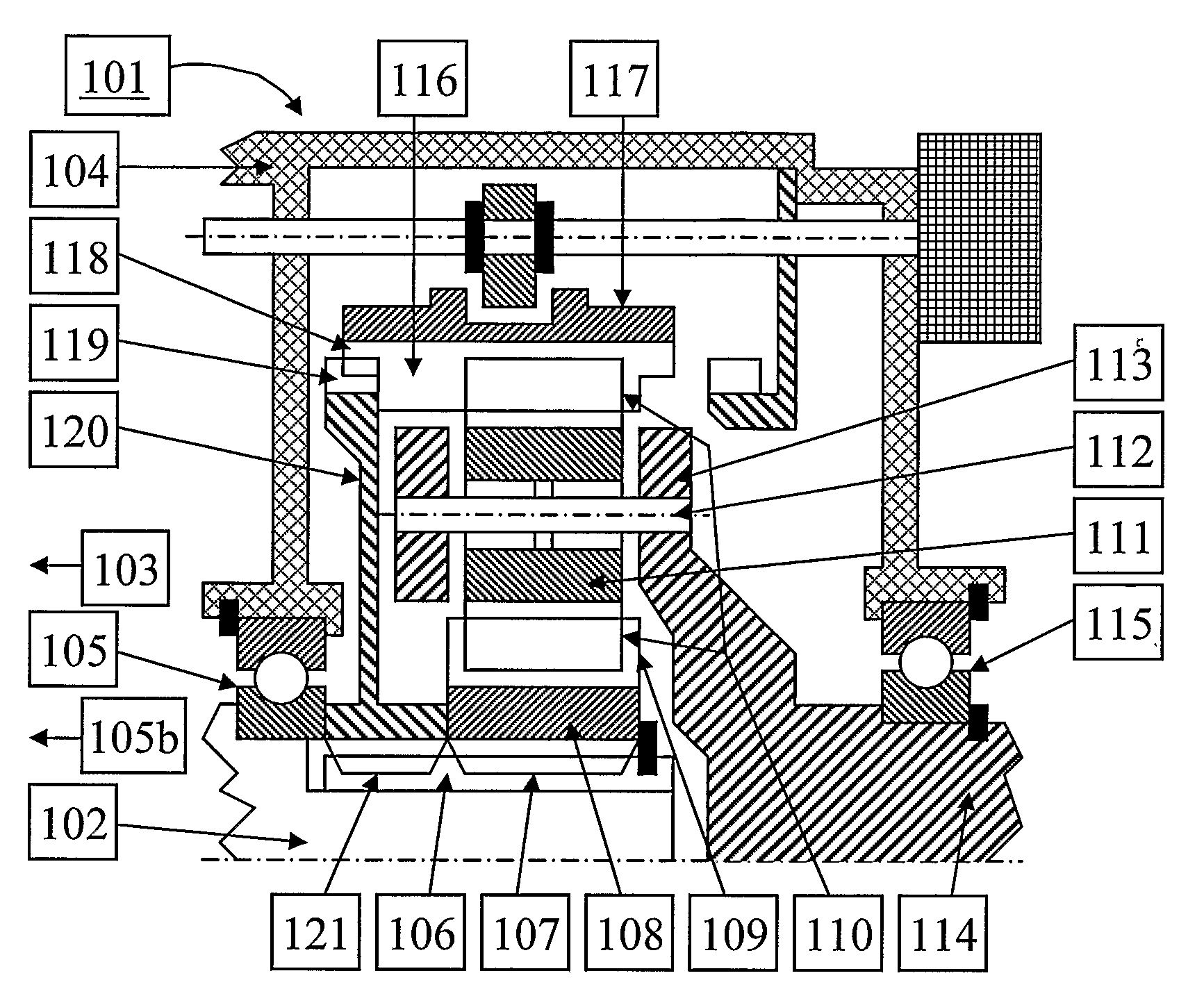
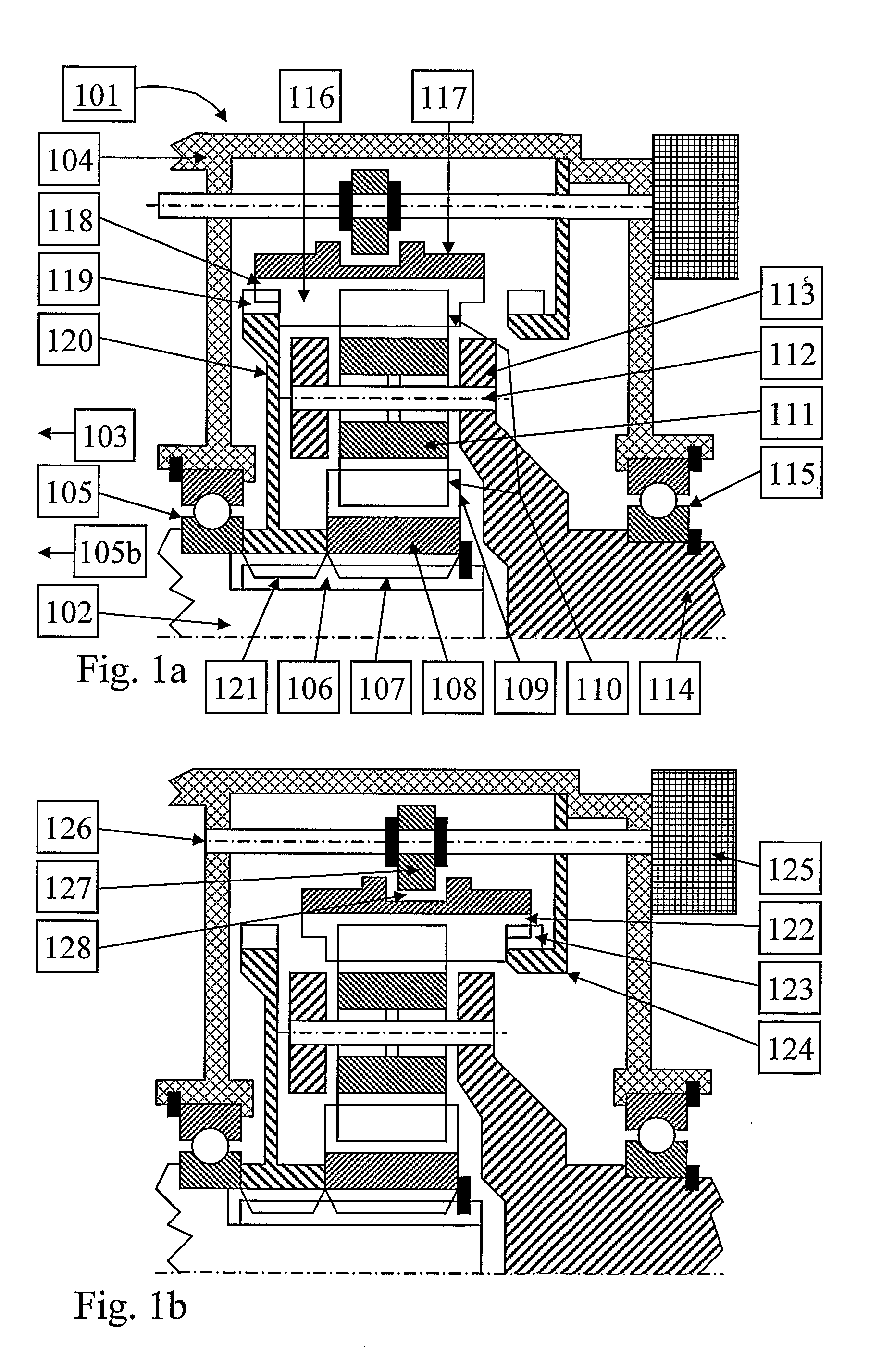
[0020]U.S. Pat. No. 5,083,993 presents a planetary gear 1 that is similar to the planetary range section 101 in FIG. 1a. In order to reduce possible misalignment, a roller bearing has been included between a planet wheel carrier 9 (corresponding to the planet carrier 113 in FIG. 1a) that is integral with an output shaft 3 (corresponding to 114 in FIG. 1a) and a sun wheel 5 (corresponding to the sun gearwheel 108 in FIG. 1a) that is arranged in a rotationally fixed manner on an input shaft 2 (corresponding to the main shaft 102 in FIG. 1a). Thus, the roller bearing acts as a radial support device for a supported shaft, the output shaft 3, on a supporting shaft, the input shaft 2. However, the roller bearing will imply increased cost.
[0021]EP-239555B1 discloses a similar planetary gear 2. Therein, with the aid of a ball bearing 18 a clutch ring 16 supports a planet wheel keeper 10 that is fastened to a planet wheel carrier 11 which, in turn, is integrated with an output shaft 4. The clutch ring 16 is non-rotatably mounted on a sun wheel 7 that is non-rotatably mounted on an input shaft 3. In FIG. 1a the equivalence would be an additional ball bearing between the engaging ring 120 and the part of the planet carrier 113 that is to the left of the planet gearwheel 111. The additional ball bearing 18 will provide a radial support of the output shaft 4 and thereby reducing the possible misalignment. However, the ball bearing 18 will imply increased cost.

Problems solved by technology

Unfortunately, the material volume that can be plastically deformed in a rolling operation is small.
There are some applications where conventionally made back-tapered clutch teeth have been shown to have insufficient self-retaining action.
Some retarder operating conditions have shown to cause problems in a planetary range section as in FIG. 2.
This urge for relative motion may turn into an unstable state if the friction between the contacting clutch teeth is large and the self-retaining action from for instance back-taper is insufficient.
Thereby, no torque can be transferred by the range section 301, and, consequently, no engine braking is possible.
A proper conventional radial support device between those shafts, such as a radial bearing (458), is either missing or insufficient under some conditions.
These contact forces tend to misalign the engaging sleeve.
Under certain conditions this misalignment might lead to gear hopout, that is, unwanted and uncontrolled disengagement of the tooth clutch.
However, the additional spindle will imply increased production cost.
However, the roller bearing will imply increased cost.
However, the ball bearing 18 will imply increased cost.

Method used


Image

  • Device for Preventing Gear Hopout in a Tooth Clutch in a Vehicle Transmission
  • Device for Preventing Gear Hopout in a Tooth Clutch in a Vehicle Transmission
  • Device for Preventing Gear Hopout in a Tooth Clutch in a Vehicle Transmission

Examples


Embodiment Construction

[0028]The potential gear hopouts that have been described above can be counteracted by having the shift actuator activated also between shifts. Thereby, axial motion of the engaging sleeve or ring gearwheel can be limited, and gear hopouts can be prevented. This is illustrated in FIG. 5 for a planetary range section 501 similar to the ones in FIG. 2 and FIG. 3. The range shift actuator 525 is activated, and a force 571 is applied on the range shift rod 526. In case of an urge for axial motion out of engagement of the ring gearwheel 517, such an axial motion will be prevented by the force 571. Hence, a gear hopout is prevented. A similar solution could also be applied on the splitter unit 450 in FIG. 4.

[0029]In a preferred embodiment, the range shift actuator 525 in FIG. 5 is only activated between shifts when the retarder is in operation, that is, when there is a gear mesh force 540 acting on the retarder driver gearwheel 533. Thereby, unnecessary activation of the range shift actua...


PUM


Abstract

A device is provided for preventing gear hopout in a tooth clutch in a vehicle transmission. The tooth clutch includes an engaging sleeve having sleeve clutch teeth that can selectably be brought in and out of an engaged state with mating clutch teeth by axial displacement of the engaging sleeve. Axial displacement is carried out by a shift actuator system. The shift actuator system is activated at some cases when the tooth clutch is in the engaged state in order to prevent gear hopout.

Description

BACKGROUND AND SUMMARY[0001]The present invention relates to vehicle transmissions, and more particularly to a device for preventing gear hopout in tooth clutches that are subjected to misalignment due to forces acting on rotating parts they connect.[0002]Tooth clutches are frequently used in stepped vehicle transmissions to engage and disengage the gears. A tooth clutch can rotatably connect a main part with a substantially coaxial connectable part. Normally, an engaging sleeve is used as an interconnecting member between these two parts. This engaging sleeve is often rotatably fixed but axially moveable with respect to said main part by means of, for instance, splines. There are clutch teeth at the end of the engaging sleeve that faces the connectable part. These clutch teeth need to be compatible with corresponding clutch teeth on the connectable part. These two sets of clutch teeth can be brought into mesh with each other by moving the engaging sleeve in axial direction towards ...

Claims


Application Information

Patent Timeline
Patent Type & Authority Applications(United States)
IPC IPC(8): F16H61/18
CPCF16D11/10F16D2011/002F16D2500/506Y10T477/6934F16H61/28F16H63/38F16D2500/70404
Inventor ALFREDSSON, SVERKERSTERVIK, HANS
Owner VOLVO LASTVAGNAR AB
Why Eureka
Try Eureka