Device and method for lumbar interbody fusion

a technology of lumbar interbody and lumbar spine, which is applied in the field of lumbar spine interbody fusion devices and methods, can solve the problems of large incisions and complicated procedures, and achieve the effect of reducing recovery time and reducing trauma to patients

Inactive Publication Date: 2008-11-27
WARSAW ORTHOPEDIC INC
View PDF13 Cites 20 Cited by
  • Summary
  • Abstract
  • Description
  • Claims
  • Application Information

AI Technical Summary

Benefits of technology

[0010]It is, therefore, an object of the present invention to provide a minimally invasive, percutaneous surgical procedure for performing interbody fusion which reduces the trauma to the patient and reduces recovery time.
[0012]It is a further object of the present invention to provide a device which facilitates the percutaneous interbody fusion procedure.
[0013]It is yet another object of the present invention to provide a device which distracts the disc space and which may be inserted through a tube to effect the percutaneous interbody fusion procedure.
[0014]It is a further object of the present invention to provide a collapsible and expandable interbody fusion spacing device that facilitates the percutaneous interbody fusion procedure.
[0016]The above and other objects of the present invention may be achieved by providing a collapsible and expandable interbody fusion spacer device that may be inserted through a small diameter tube to the disc space that is being fused, so that the procedure may be performed in a minimally invasive manner. The spacer is preferably constructed in two halves that are connected by pins located on the sides of the spacer. The outer surface may be flat to engage the end plate of the vertebra above and below the spacer, and the outer surface may be scored, have ridges, points, tabs, detents, or the like to enhance gripping of the end plates of the vertebra to resist movement of the spacer once it is in place. The interior surfaces of the halves that make up the spacer include a semicircular hollowed portion that is preferably threaded along at least a portion of its length that is aligned with a similar semicircular threaded hollowed portion on the other half of the spacer. When the spacer is assembled, the threaded portion forms a canal for acceptance of a piston screw. Preferably, the threaded canal is tapered from one end to the other, particularly from the end which will be positioned posteriorly in the disc space to the end which will be positioned anteriorly in the disc space. When the piston screw is inserted, the anteriorly positioned end will expand a greater distance in the disc space than the posterior end, due to the tapered threaded canal. This will cause the disc height, i.e. the distance between the vertebra, to be greater anteriorly than posteriorly, which more closely mimics the natural curve of the spine, particularly in the lumbar spine, thus restoring lordosis, the natural curve of the lumbar spine.

Problems solved by technology

The current techniques, due to the present equipment available, particularly for anterior interbody fusion, suffer the disadvantage in that they are major surgeries and require large incisions with the manipulation of both tissue and organs.
While attempts have been made to perform anterior interbody fusions laparoscopically, these procedures are often complicated and are typically performed under general anesthesia.

Method used


Image

  • Device and method for lumbar interbody fusion
  • Device and method for lumbar interbody fusion
  • Device and method for lumbar interbody fusion

Examples


Embodiment Construction

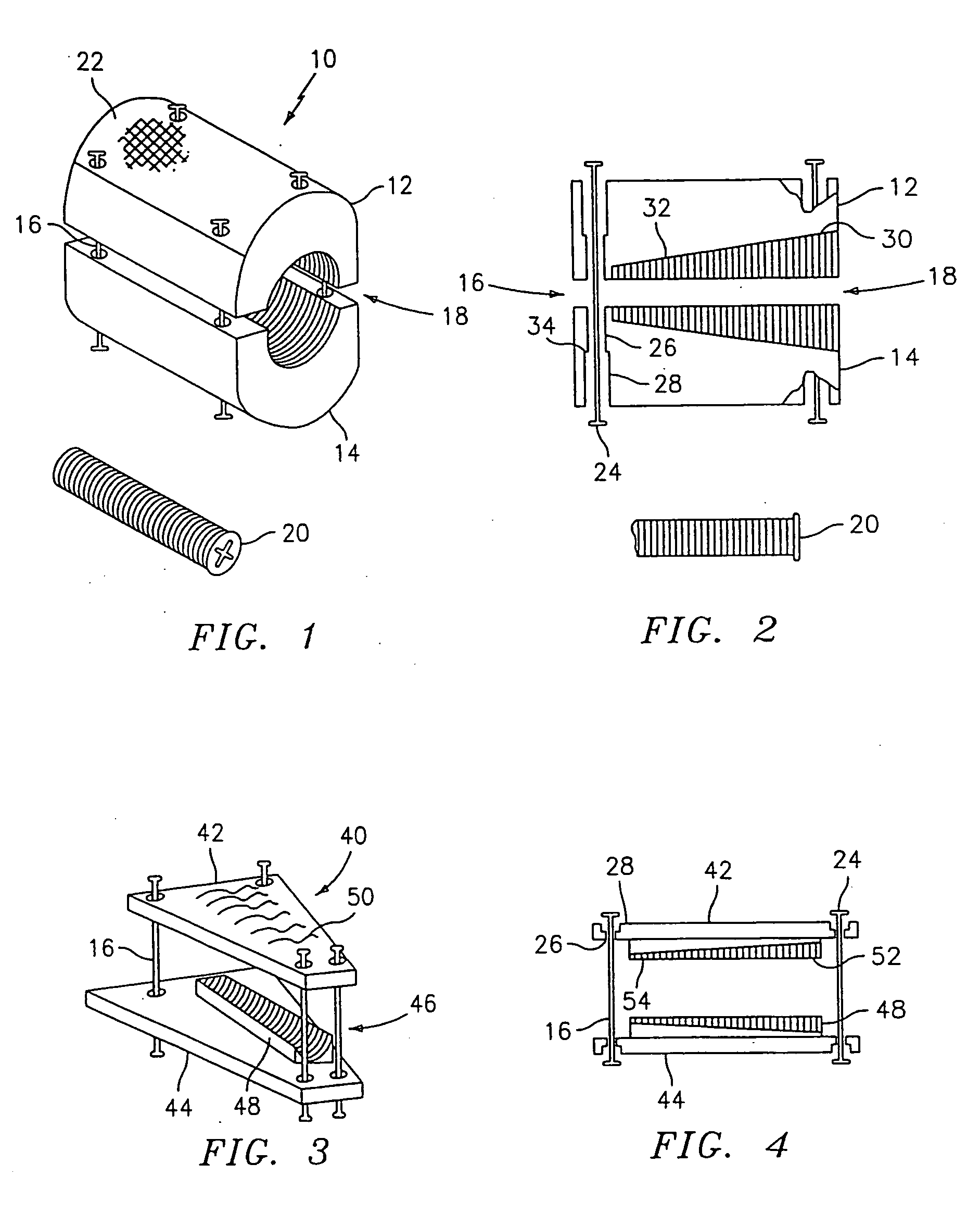
[0029]Referring now to the drawings, in which like reference numerals identify similar or identical elements throughout the several views, and inn particular to FIG. 1, there is shown the expandable intervertebral disc spacer device 10 according to the present invention. Preferably, the disc spacer 10 is comprised of two similarly shaped halves 12, 14 that are opposed to each other and loosely connected by pins 16. The outer surface of each half may be scored, as indicted by reference numeral 22, for facilitating adherence to the end plates of the vertebral bodies between which disc spacer 10 is placed. When top half 12 and bottom half 14 are assembled, together they may form a cylinder, a cube, a rectangular box, or any geometric shape that may be split to form two opposed halves. A tapered bore 18 is provided, which has a larger diameter 30 at a first end and a smaller diameter 32 at a second end. Preferably, tapered bore 18 is threaded over at least a portion of its length. While...


PUM


Abstract

A method for performing percutaneous interbody fusion is disclosed. The method includes the steps of inserting a guide needle posteriorly to the disc space, inserting a dilator having an inner diameter slightly larger than the outer diameter of the guide needle over the guide needle to the disc space to enlarge the disc space, and successively passing a series of dilators, each having an inner diameter slightly larger than the outer diameter of the previous dilator, over the previous dilator to the disc space the gradually and incrementally increase the height of the disc space. Once the desired disc height is achieved, the guide needle and all the dilators, with the exception of the outermost dilator, are removed. An expandable intervertebral disc spacer is then passed through the remaining dilator and positioned in the disc space. The disc spacer is expanded to the required disc height, and then a bone matrix is passed through the dilator to fill the disc space. The dilator is then removed. An expandable intervertebral disc spacer is also disclosed, having a tapered bore that causes greater expansion of one end of the spacer with respect to the other. A kit for performing the percutaneous interbody fusion procedure is also disclosed.

Description

BACKGROUND OF THE INVENTION[0001]1. Field of the Invention[0002]The present invention relates to a device and method for performing interbody spinal fusion, stabilization and restoration of the disc height in the spine, and in particular to a device and method for performing percutaneous, minimally invasive interbody fusion of the lumbar spine.[0003]2. Discussion of the Related Art[0004]Many devices exist to assist in maintaining the position of the lumbar vertebra in conjunction with lumbar fusion surgery. Fusion is the joining together of the vertebra of the spine. The underlying concept of the known devices is to maintain the relative position of the vertebral bodies with respect to each other, while the bone that has been placed between the vertebra to form the fusion of the vertebra, has an opportunity to heal and mature. These devices employ different strategies and philosophies, and can include devices which utilize the pedicles, as well as devices which are placed in to the ...

Claims


Application Information

Patent Timeline
Patent Type & Authority Applications(United States)
IPC IPC(8): A61B17/58A61B19/00A61F2/44A61M29/00A61B17/56A61B17/02A61B19/02A61F2/00A61F2/02A61F2/28A61F2/30A61F2/46
CPCA61B19/0271A61B2017/0256A61B2019/0202A61F2/0095A61F2/28A61F2/30771A61F2/446A61F2/447A61F2/4611A61F2002/2835A61F2002/2839A61F2002/30238A61F2002/30372A61F2002/30492A61F2002/30507A61F2002/30538A61F2002/30556A61F2002/30579A61F2002/30975A61F2002/448A61F2002/4635A61F2220/0025A61F2220/0033A61F2230/0069A61F2250/0006A61F2250/0009A61F2310/00023A61F2310/00359A61B50/33A61B2050/005A61F2002/30237
Inventor BOEHM, JR., FRANK H.MELNICK, BENEDETTA DELORENZO
Owner WARSAW ORTHOPEDIC INC
Why Eureka
Try Eureka