
Methods, Systems, and Apparatus for Implanting Prosthetic Devices Into Cartilage

a prosthetic device and cartilage technology, applied in the field of medical prosthetic devices, can solve the problems of inability to meet the needs of patients, inability to perform the procedure, and inability to fully recover, so as to preserve and/or regenerate bone strength, strengthen and/or elasticity, and reduce the effect of bone stress and strain

Active Publication Date: 2008-11-27
ACTIVE IMPLANTS LLC
View PDF50 Cites 157 Cited by
  • Summary
  • Abstract
  • Description
  • Claims
  • Application Information

AI Technical Summary

Benefits of technology

[0006]In some instances, the prosthetic device is an implantable artificial acetabular socket made of a pliable structural material validated for medical devices used in vivo and having mechanical properties characterized by a non-linear stress-strain relationship defined by a polynomial mathematical curve having more than two coefficients, such as the Mooney Rivlin coefficients. In some instances, the material has strength and / or elasticity substantially similar to human cartilage. In some instances, the material is a polyurethane based material, which may be polycarbonate polyurethane in some embodiments, and may be a Bionate Polyurethane in some embodiments. The material of the prosthetic device and the natural articular cartilage layer operate together to dissipate bone stress and strain associated with the hip joint during the life of the device to help preserve and / or regenerate bone strength.

Problems solved by technology

Various conditions can cause damage to the hip joint resulting in debilitating pain, arthritis, and / or limited mobility.
Removal of the bone can make the procedure painful, invasive, and irreversible.
Although existing methods and devices associated with prosthetic hip joint components have been adequate in some respects, they have not been satisfactory in all respects.

Method used


Image

  • Methods, Systems, and Apparatus for Implanting Prosthetic Devices Into Cartilage
  • Methods, Systems, and Apparatus for Implanting Prosthetic Devices Into Cartilage
  • Methods, Systems, and Apparatus for Implanting Prosthetic Devices Into Cartilage

Examples


Embodiment Construction

[0031]For the purposes of promoting an understanding of the principles of the present disclosure, reference will now be made to the embodiments illustrated in the drawings, and specific language will be used to describe the same. It will nevertheless be understood that no limitation of the scope of the disclosure is intended. Any alterations and further modifications in the described devices, instruments, methods, and any further application of the principles of the disclosure as described herein are contemplated as would normally occur to one skilled in the art to which the disclosure relates. In particular, it is fully contemplated that the features, components, and / or steps described with respect to one embodiment may be combined with the features, components, and / or steps described with respect to other embodiments of the present disclosure.

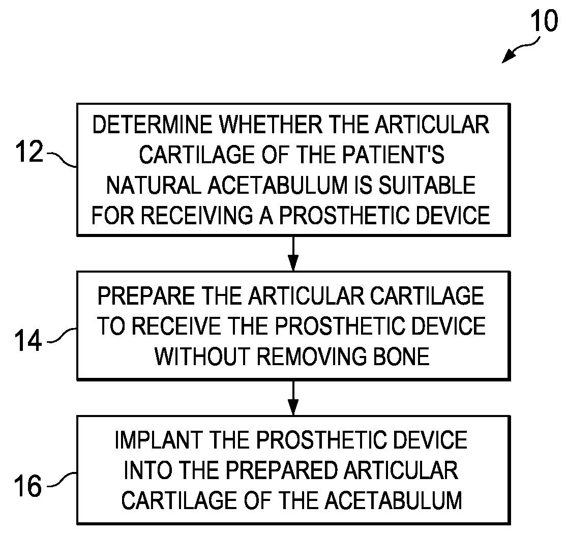
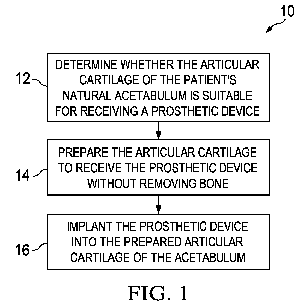
[0032]Referring now to FIG. 1 shown therein is a flowchart representative of a method 10 according to one embodiment of the present disclosu...


PUM


Abstract

A method of implanting a prosthetic acetabular cup into a patient is disclosed. The method comprises gaining access to an acetabulum of the patient, where the acetabulum includes an inner portion formed of bone and an outer portion formed of articular cartilage. The method also comprises creating a recess within the articular cartilage of the outer portion of the acetabulum without removing any portion of bone from the inner portion of the acetabulum. The recess is shaped to mate with a snap-fit structure of the prosthetic acetabular cup. Finally, the method comprises securely engaging the prosthetic acetabular cup with the acetabulum by snap-fitting the snap-fit structure of the prosthetic acetabular cup with the recess in the articular cartilage of the outer portion of the acetabulum.

Description

PRIORITY[0001]The present application claims priority to U.S. Provisional Application No. 60 / 939,323 filed May 21, 2007, which is hereby incorporated by reference in its entirety.TECHNICAL FIELD[0002]Embodiments of the present disclosure relate generally to medical prosthetic devices, including prosthetic hip joint components, and associated methods of implantation and treatment.BACKGROUND[0003]The present disclosure relates to devices and methods of implanting medical prosthetic devices that replace at least some of the functionality of the natural hip joint. The natural hip joint is a ball-and-socket joint formed by the articulating interaction of the rounded head of the femur with the acetabulum of the pelvis. The articulating surfaces of both the head of the femur and the acetabulum are covered with articular cartilage. Various conditions can cause damage to the hip joint resulting in debilitating pain, arthritis, and / or limited mobility. In some instances, hip arthroplasty has ...

Claims


Application Information

Patent Timeline
IPC IPC(8): A61F2/32A61B17/58
CPCA61B17/1666A61F2/30756A61F2/30965A61F2/34A61F2002/305A61F2002/30757A61F2002/30822A61F2002/30878A61F2002/3422A61F2002/3446A61F2220/0025A61F2002/342
Inventor STEINBERG, AMIRAM
Owner ACTIVE IMPLANTS LLC
Learn More