
System for Managing the Terminal Part of a Flight Plan

a technology for managing the terminal and the flight plan, which is applied in the direction of process and machine control, instruments, navigation instruments, etc., can solve the problems of not being able to take into account the risks of operation, not being able to comply with the crew, and having undesirable effects

Active Publication Date: 2008-11-27
THALES SA
View PDF12 Cites 16 Cited by
  • Summary
  • Abstract
  • Description
  • Claims
  • Application Information

AI Technical Summary

Problems solved by technology

This operation can have undesirable effects insofar as it provokes a reiteration of the operation of chaining published navigation procedures over the terminal part of the route predicted in the flight plan.
Not being reiterated to the crew of the aircraft, there is a risk that they are not taken into account when there is a change of approach procedure.
Thus, an altitude constraint, imposed by an air traffic control authority on passing a “waypoint” forming part of the initial approach procedure not recalled by the control authority asking for the change of landing runway whereas the “waypoint” is still part of the new approach procedure, runs a certain risk of not being complied with out informing the crew.
These problems exist with no matter what change of terminal procedure (departure, arrival, approach) as soon as any modification whatsoever has been made (constraint, adding of intermediate waypoints) and which applies to a portion common to the old procedure and to the new procedure.
This technique is little appreciated because it amounts to causing the same waypoints to appear several times in an alphanumeric table of the flight plan, or even to cause whole sequences of waypoints which will not be flown to appear in this table and to oblige the crew to differentiate between the active and inactive waypoints when it is monitoring the correct progress of the flight plan, which increases its workload during difficult phases such as an approach flight phase.

Method used


Image

  • System for Managing the Terminal Part of a Flight Plan
  • System for Managing the Terminal Part of a Flight Plan
  • System for Managing the Terminal Part of a Flight Plan

Examples


Embodiment Construction

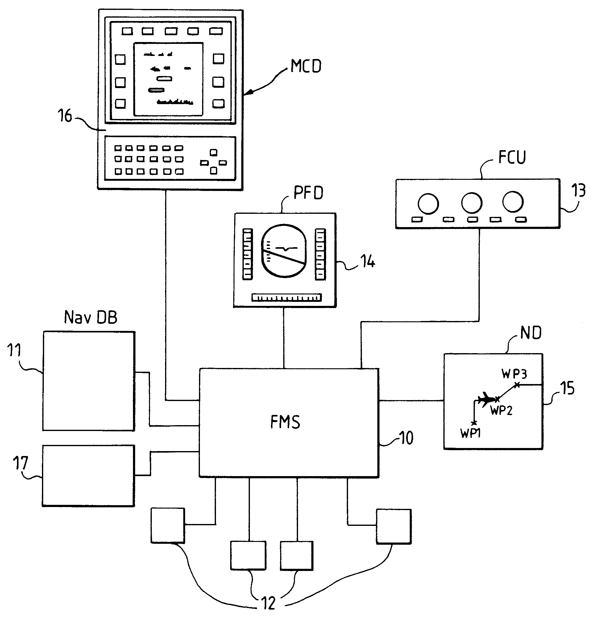
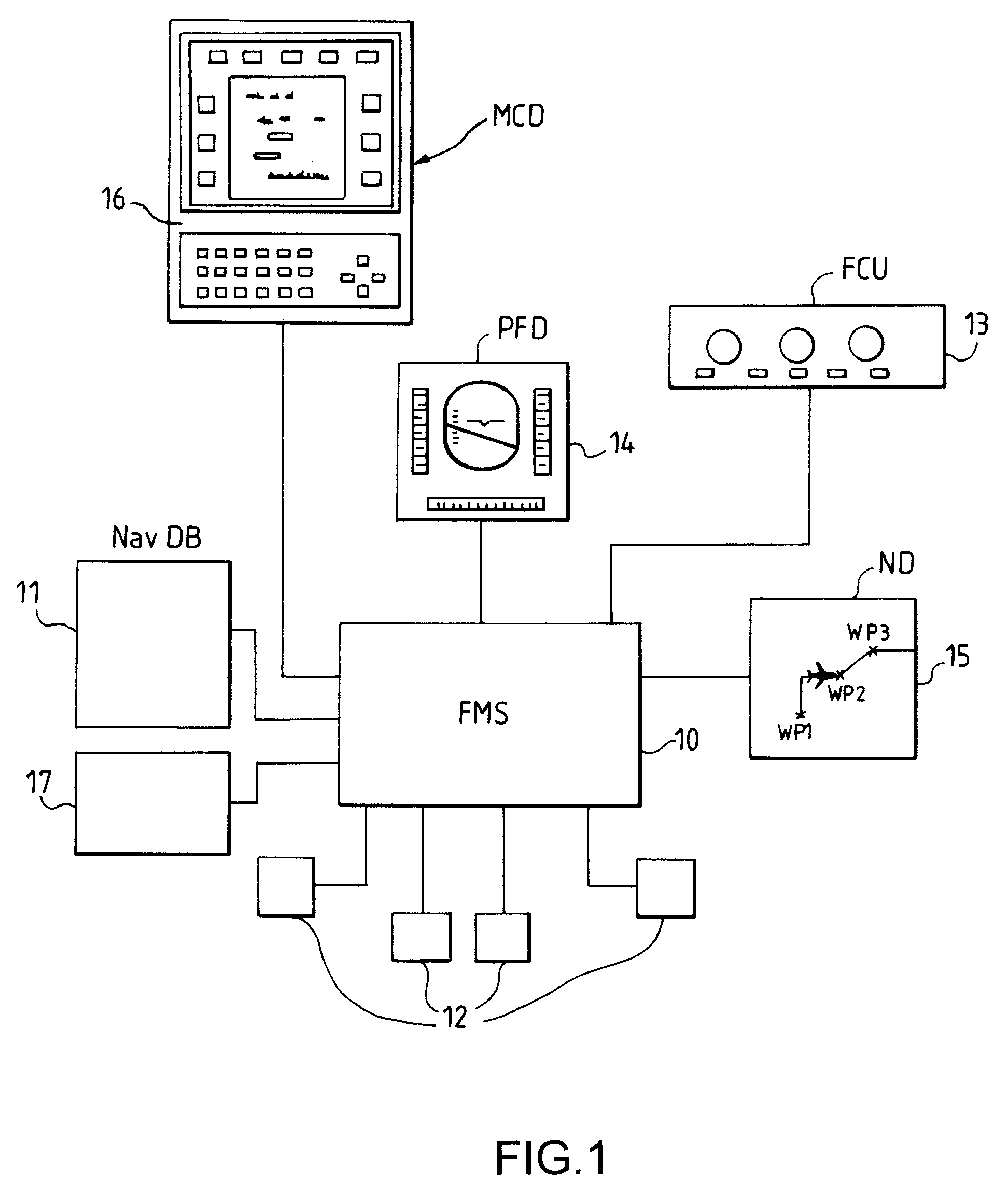
[0026]As shown in FIG. 1, an on-board flight management system comprises an FMS flight management computer 10. The latter exchanges various data with a navigation database 11 called NavDB (the acronym for “Navigation Database”), with a mirror memory 17 and with other items of equipment 12 of the aircraft. It communicates with the crew of the aircraft by the intermediary of man-machine interfaces among which are principally found:[0027]an FCU control panel 13 with switches, knobs, display devices and indicator lamps allowing the selection and parameterization of the principal operating modes of the FMS computer 10 and of the automatic pilot and / or flight manager upon which the FMS computer 10 acts but which is not shown in order not to uselessly clutter FIG. 1,[0028]a PFD primary piloting screen 14 used for displaying an artificial horizon and flight parameters such as the altitude of the aircraft, its attitude, its speed vector, a guidance mode indication, etc.,[0029]an ND navigatio...


PUM


Abstract

The management system plots the route to be flown in a flight plan, at least partially, by a chaining of published navigation procedures accessible from a NavDB navigation database and constituted of sequences of waypoints and / or turn points associated with specific flight constraints. It comprises a mirror memory storing the latest versions of the published navigation procedures, modified by the crew of the aircraft during the progress of the flight plan and means of substituting these latest versions stored in the mirror memory for the published versions of the navigation procedures during a change in the route predicted in the flight plan obtained by a new chaining of navigation procedures, some of which are taken from the preceding chaining. This makes it possible, during a change of navigation procedure, to take account of specific flight constraints already entered during the progress of the flight but not appearing in the published navigation procedures.

Description

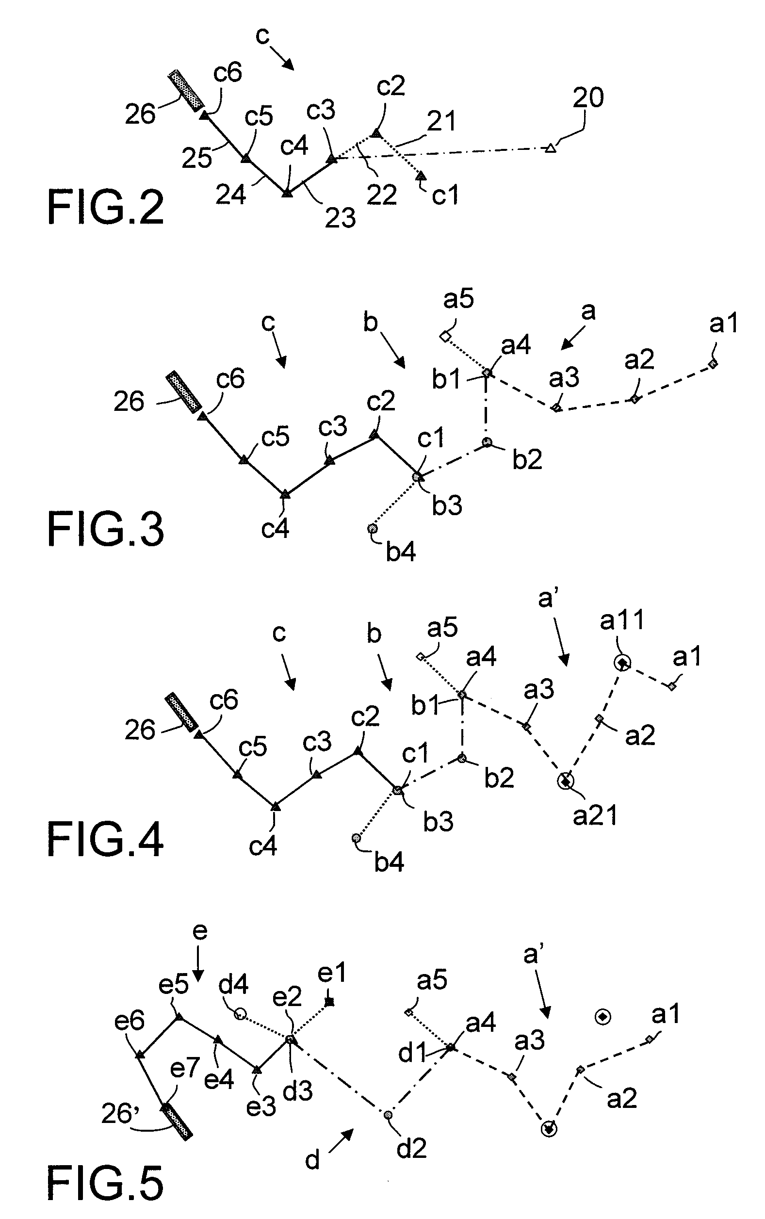
CROSS-REFERENCE TO RELATED APPLICATIONS[0001]The present Application is based on International Application No. PCT / EP2006 / 068456, filed on Nov. 14, 2006, which in turn corresponds to French Application No. 0512418 filed on Dec. 11, 2006, and priority is hereby claimed under 35 USC §119 based on these applications. Each of these applications are hereby incorporated by reference in their entirety into the present application.FIELD OF THE INVENTION[0002]The present invention relates to the following of a flight plan taking account of navigation instructions and procedures imposed by the air traffic control authorities.BACKGROUND OF THE INVENTION[0003]A flight plan defines the route which the crew of an aircraft foresees following in order to go from its departure point to the destination point of its mission as well as the conditions for flying this route by a succession of waypoints or turn points, connected by straight or curved segments called “legs” and associated with various flig...

Claims


Application Information

Patent Timeline
Patent Type & Authority Applications(United States)
IPC IPC(8): G08G5/00
CPCG01C21/14G08G5/0039G05D1/0676
Inventor BITAR, ELIASLERICHE, STEPHANECAILLAUD, CHRISTOPHE
Owner THALES SA
Learn More