
Data Transmission Method and Data Transmission System

Inactive Publication Date: 2008-11-27
ADVANTEST CORP
View PDF4 Cites 0 Cited by
  • Summary
  • Abstract
  • Description
  • Claims
  • Application Information

AI Technical Summary

Benefits of technology

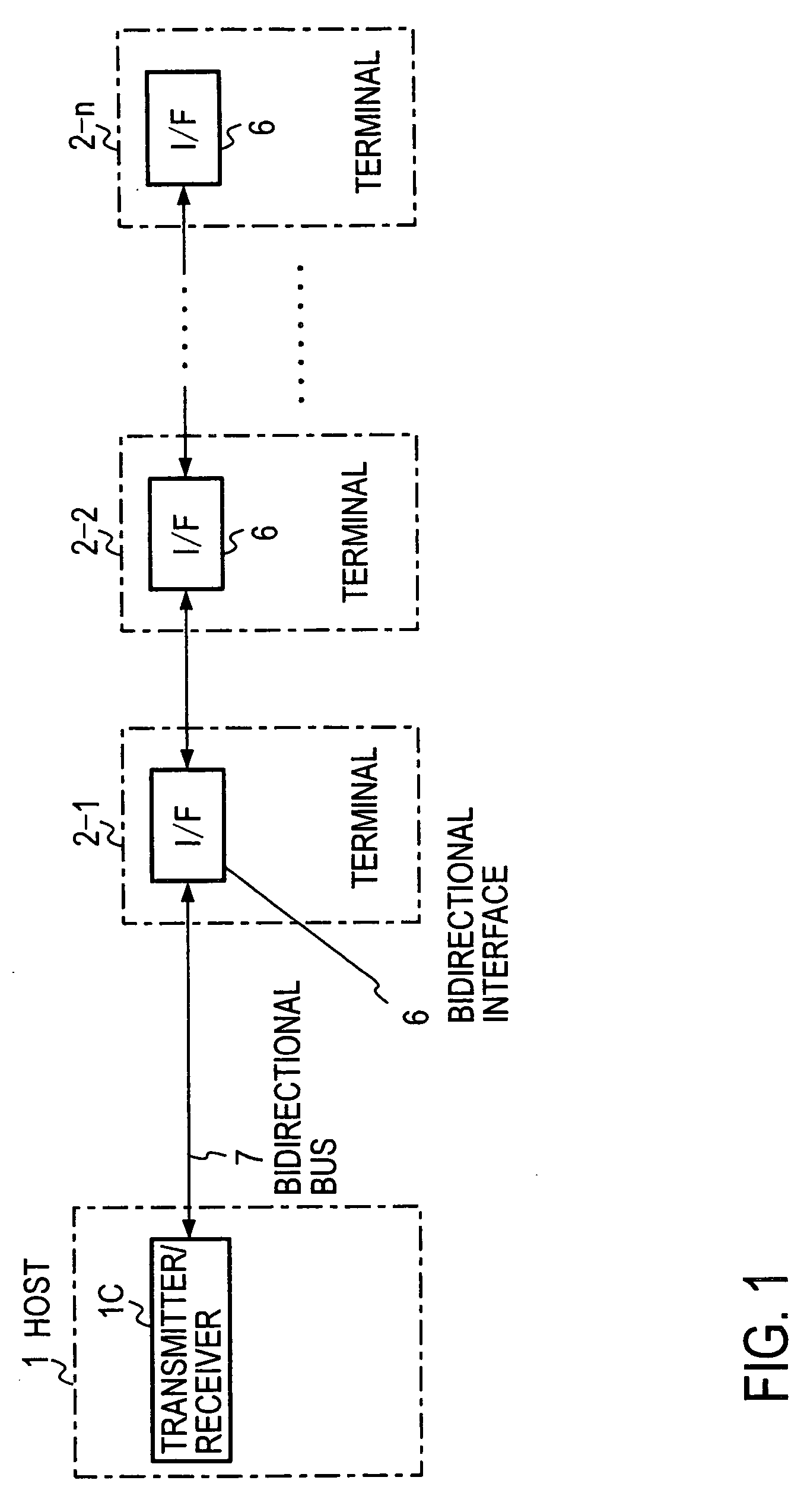
[0009]According to the present invention, only the return signal generator section provided in the terminal located connected to the data bus line at the distal end thereof is controlled to be kept in the enabled state and originates the return signal at the time when a signal from the host arrives at the terminal located at the distal end. The return signal is returned to the host via the same data bus line. Any terminal to transmit data to the host transmits the data in synchronization with the return signal passing through the interface thereof. The host can read the data if arrival of the return signal is detected. A bit position is assigned to the data transmitted from each terminal. Thus, from the bit position of the data read by the host, the host can recognize which terminal has transmitted the data.
[0010]Thus, a single data bus line can be used for bidirectional transmission, and the amount of cables used as the data bus line can be reduced to a half. In addition, the cables can be thinner, so that the cables can be installed more easily. Furthermore, a new terminal can be advantageously easily added.
[0011]A data transmission system according to the present invention can be applied to fields of measurement equipment and control equipment that involve data transmission between multiple terminals.

Problems solved by technology

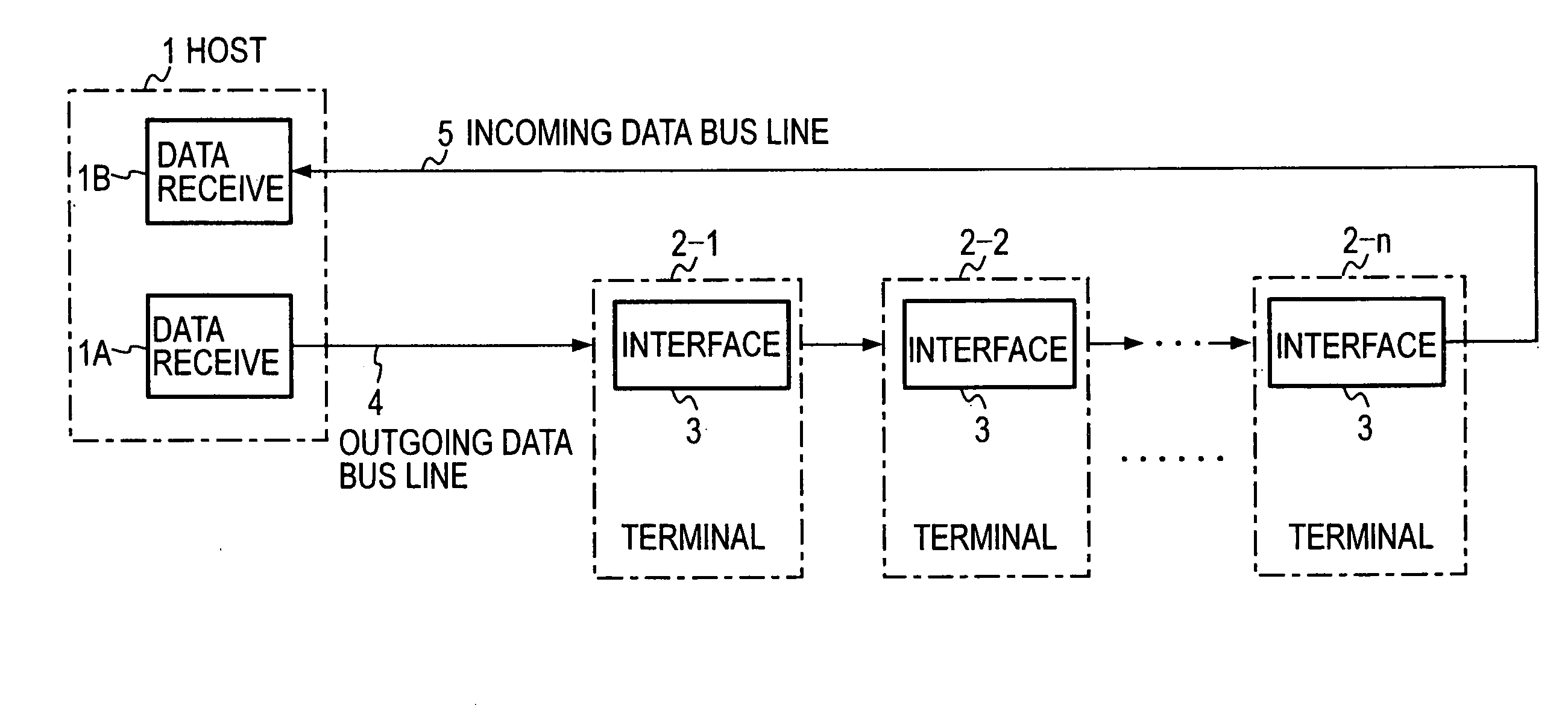
Therefore, there is a disadvantage that the amount of the data bus lines provided is doubled, and a thick cable is required if the outgoing data bus line 4 and the incoming data bus line 5 are tied together.
In addition, there is another disadvantage that cable replacement is required for adding a terminal, so that it is troublesome to add a terminal.

Method used


Image

  • Data Transmission Method and Data Transmission System
  • Data Transmission Method and Data Transmission System
  • Data Transmission Method and Data Transmission System

Examples


first embodiment

[0031]FIG. 1 is a schematic block diagram for illustrating a data transmission method according to the present invention, in which parts corresponding to those shown in FIG. 11 are denoted by the same reference numerals as in FIG. 11. A host 1 and terminals 2-1, 2-2, . . . , 2-n are the same as those in FIG. 11. However, according to the present invention, the host 1 and the n terminals 2-1, 2-2, . . . , 2-n are cascaded to each other via a bidirectional bus 7, and each terminal 2-1, 2-2, . . . , 2-n has a bidirectional interface 6. Therefore, the host 1 has a transmitter / receiver IC as means for transmitting and receiving data.

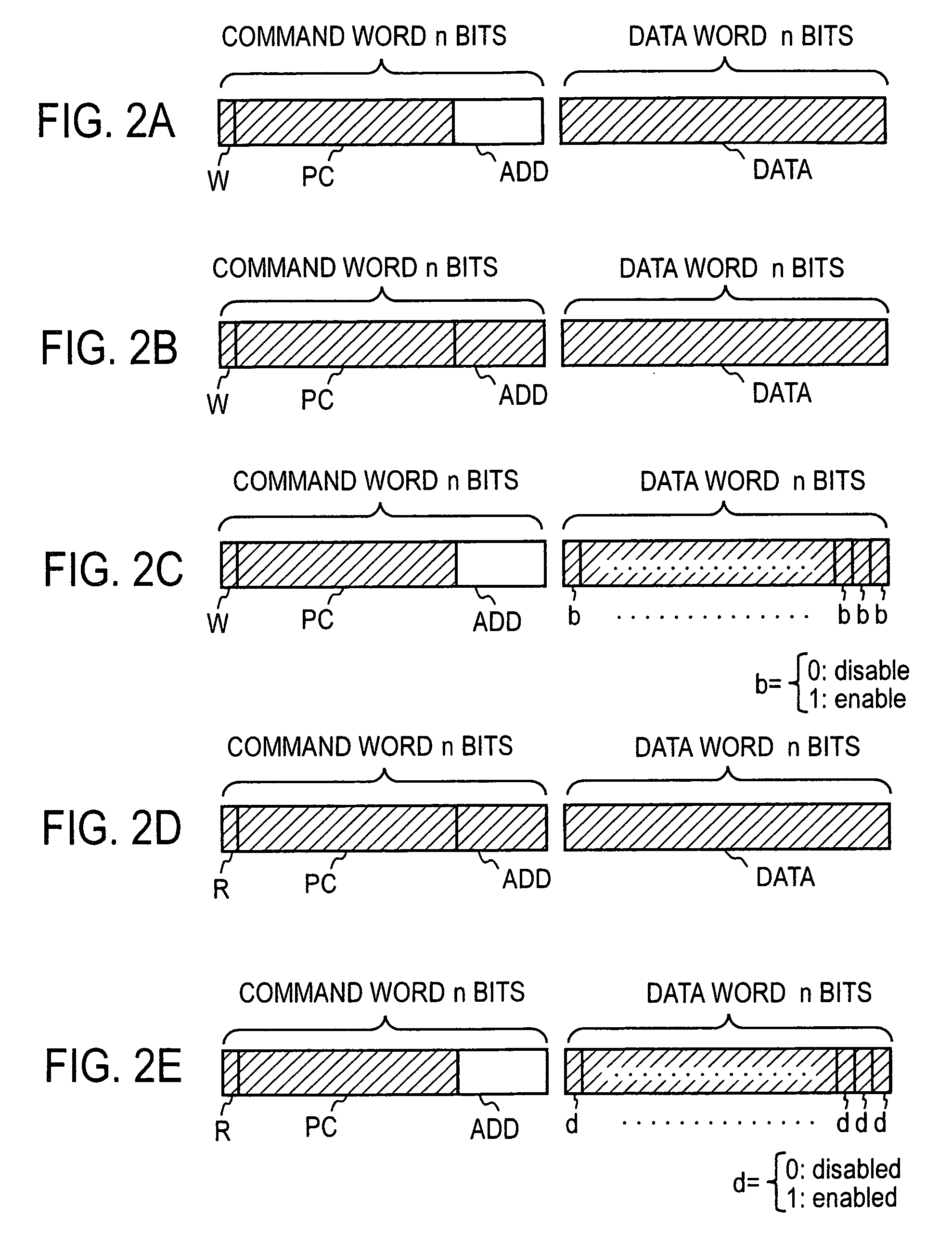
[0032]The host 1 transmits a parallel n-bit command word (simply referred to also as command hereinafter) and a parallel n-bit data word (simply referred to also as data hereinafter) to the terminals 2-1, 2-2, . . . , 2-n (this direction of transmission will be referred to as downward direction hereinafter). Each terminal 2-1, 2-2, . . . , 2-n takes in data a...


PUM


Abstract

A terminal of a plurality of terminals that is located at the farthest position from a host has a return signal generator section, the return signal generator section transmits a return signal at a timing when data transmitted from the host to the terminals arrives at the terminal located at the farthest position, the return signal is returned to the host successively passing through interfaces of the terminals connected to a data bus, and each terminal originates data to be transmitted from the terminal to the host or from the terminal to a particular another terminal in synchronization with the return signal and delivers the data from the terminals to the host or the terminal in synchronization with the return signal.

Description

TECHNICAL FIELD[0001]The present invention relates to a data transmission method and a data transmission system that can be suitably applied to an apparatus composed of a plurality of units interconnected via a data bus line to serve a common purpose, such as an IC testing apparatus.BACKGROUND ART[0002]FIG. 11 is a schematic diagram showing a data transmission path of an IC testing apparatus conventionally used. In this drawing, reference numeral 1 denotes a host computer, reference numeral 1A denotes a data transmitter section in the host computer, and reference numeral 1B denotes a data receiver section. Reference numerals 2-1, 202, . . . , 2-n each denote a terminal that operates under instructions from the host computer 1. In this example of the IC testing apparatus, the terminal 2-1 may serve as a pattern generator section, the terminal 2-2 may serve as a timing generator section, and the terminal 2-n may serve as a test head, for example.[0003]Each terminal 2-1, 2-2, . . . , 2...

Claims


Application Information

Patent Timeline
IPC IPC(8): G06F13/38G06F3/00
CPCG06F11/221G06F13/4072
Inventor SHIMOYAMA, SATOSHI
Owner ADVANTEST CORP
Learn More