Injector cleaning system based on pressure decay

a technology of pressure decay and injector, which is applied in the direction of machines/engines, engine components, mechanical equipment, etc., can solve the problems affecting the performance of the engine, and affecting the performance of the fuel injector, so as to achieve the effect of reducing the functionality of the filter and subsequent engine performance, and reducing the performance of the engin

Inactive Publication Date: 2008-12-04
CATERPILLAR INC
View PDF5 Cites 26 Cited by
  • Summary
  • Abstract
  • Description
  • Claims
  • Application Information

AI Technical Summary

Problems solved by technology

However, the use of the particulate trap for extended periods of time may cause the particulate matter to build up in the medium, thereby reducing functionality of the filter and subsequent engine performance.
This remaining fuel, when subjected to the harsh conditions of the exhaust stream, may coke or be partially burned, leaving behind a solid residue that can restrict or even block the fuel injector.
Although the apparatus of the '872 patent may allow for testing and cleaning of injectors and does so in situ, it still may be limited.
Specifically, because the apparatus only tests injector performance when manually triggered to do so, there may be situations when the injectors could be unknowingly operating sub-optimally such as between standard scheduled diagnostic / service events.
In addition, because the apparatus only checks the quality of a cleaning based on a technician's desire to do so, the quality checks may be periodically skipped or omitted altogether, thereby allowing for a malfunctioning injector to continue performing poorly.
Further, because the apparatus of the '872 patent provides only a single level of cleaning, severely clogged injectors may be treated the same as injectors having only a slight restriction.
For this reason, some injectors may be cleaned inadequately, while cleaning fluid may be unnecessarily wasted on other injectors.
The apparatus of the '872 patent may also be expensive and interruptive.
Unnecessary cleanings waste cleaning fluid, thereby increasing operational cost of the system.
And, because cleaning causes isolation of the tested injector, engine operation may be interrupted each time a cleaning is initiated.

Method used


Image

  • Injector cleaning system based on pressure decay
  • Injector cleaning system based on pressure decay
  • Injector cleaning system based on pressure decay

Examples


Embodiment Construction

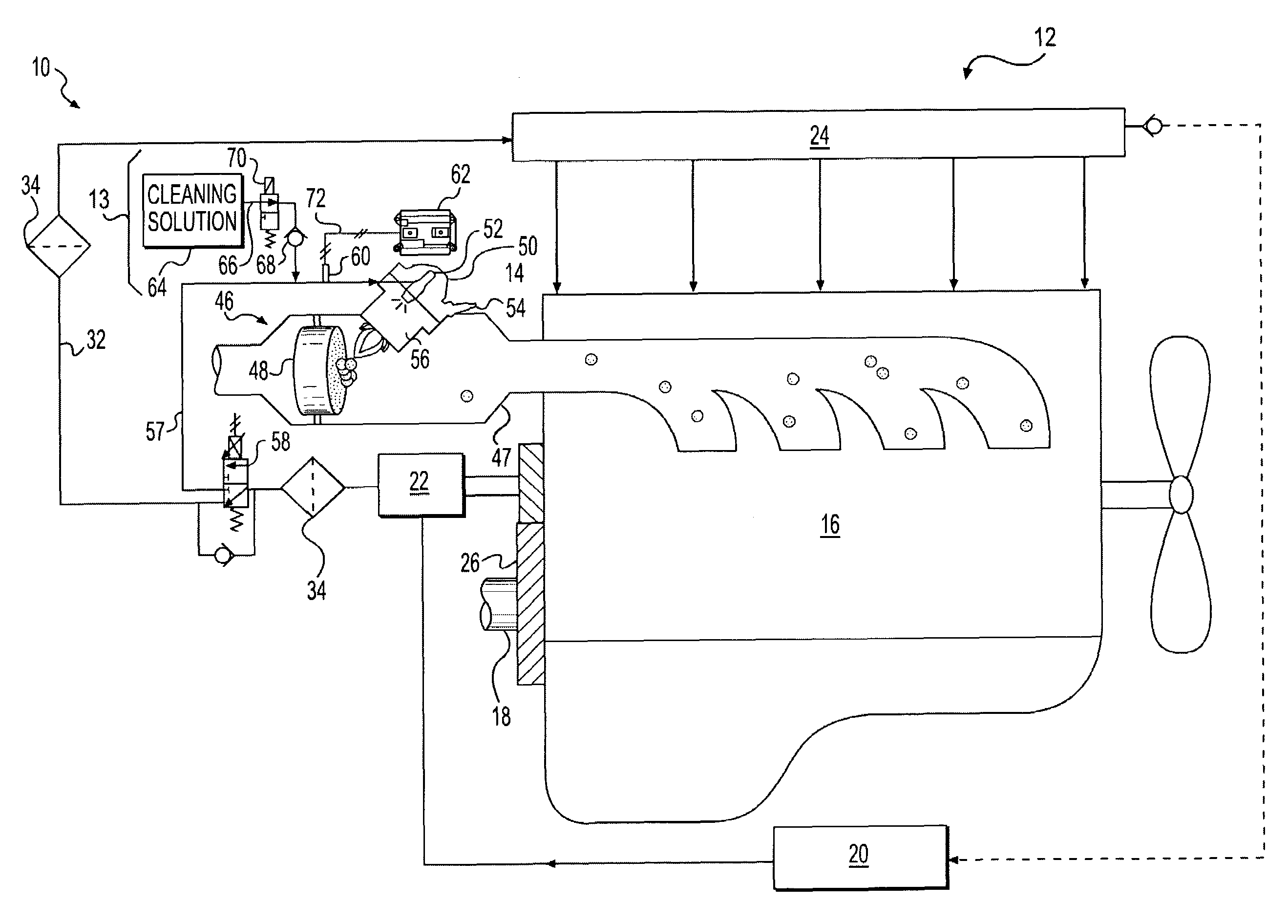
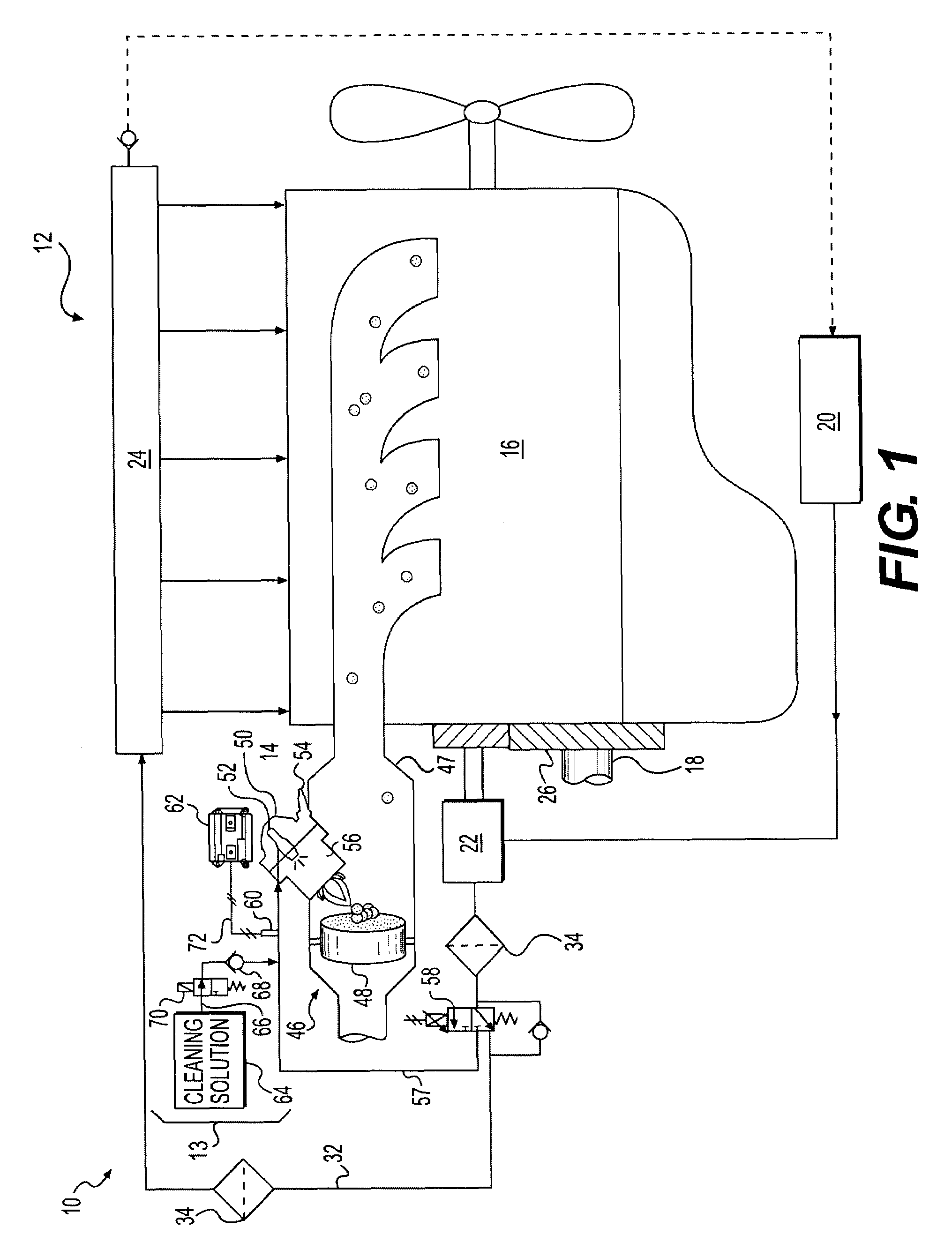
[0015]FIG. 1 illustrates a power unit 10 having a common rail fuel system 12, an injector cleaning system 13 and an auxiliary regeneration device 14. For the purposes of this disclosure, power unit 10 is depicted and described as a four-stroke diesel engine. One skilled in the art will recognize, however, that power unit 10 may be any other type of internal combustion engine such as, for example, a gasoline or a gaseous fuel-powered engine. Power unit 10 may include an engine block 16 that at least partially defines a plurality of combustion chambers (not shown), and a crankshaft 18 rotatable within engine block 16.

[0016]Fuel system 12 may be a common rail fuel system that may include components that cooperate to deliver injections of pressurized fuel into each of the combustion chambers. Specifically, common rail fuel system 12 may include a tank 20 configured to hold a supply of fuel, and a fuel pumping arrangement 22 configured to pressurize the fuel and direct the pressurized fu...


PUM


Abstract

An injector cleaning system for use with an exhaust treatment device is disclosed. The injector cleaning system may have a supply of injection fluid and an injector configured to receive and inject the injection fluid. The injector cleaning system may also have a pressure sensor associated with the injector to generate a signal indicative of the pressure of the injection fluid supplied to the injector. The injector cleaning system may further have a controller in communication with the injector and the pressure sensor. The controller may be configured to determine a pressure decay rate of injection fluid supplied to the injector during a normal injection event based on the signal. The controller may be further configured to compare the determined pressure decay rate to an expected pressure decay rate, and supply cleaning fluid to the injector based on the comparison.

Description

TECHNICAL FIELD[0001]The present disclosure is directed to an injector cleaning system and, more particularly, to an injector cleaning system that cleans an injector based on a pressure decay.BACKGROUND[0002]Engines, including diesel engines, gasoline engines, gaseous fuel powered engines, and other engines known in the art exhaust a complex mixture of air pollutants. These air pollutants include solid material known as particulate matter or soot. Due to increased attention on the environment, exhaust emission standards have become more stringent and the amount of particulate matter emitted from an engine is regulated depending on the type of engine, size of engine, and / or class of engine.[0003]One method implemented by engine manufacturers to comply with the regulation of particulate matter exhausted to the environment has been to remove the particulate matter from the exhaust flow of an engine with a device called a particulate trap or diesel particulate filter. A particulate trap...

Claims


Application Information

Patent Timeline
Patent Type & Authority Applications(United States)
IPC IPC(8): F01N3/00
CPCF01N3/025F01N3/0256F01N3/36F01N2900/1808F02M65/008F01N2550/05F01N2610/1493F02M65/003
Inventor KARKKAINEN, KEVIN JAMESGRAHAM, CURTIS JOHNGONG, XIAOHUIWALTON, KYLE B.HOFSTETTER, TAMARA S.
Owner CATERPILLAR INC
Why Eureka
Try Eureka