Transmission

a technology of transmission and transmission shaft, which is applied in the field of transmission, can solve the problems of increasing the overall length of the combination of engine and transmission shaft, difficulty in adequately laying out the power train in the engine compartment of the vehicle, and the inability to downsize the second countershaft, so as to reduce the driving torque and facilitate the downsizing of the transmission

a technology of transmission and transmission shaft, which is applied in the field of transmission, can solve the problems of increasing the overall length of the combination of engine and transmission shaft, difficulty in adequately laying out the power train in the engine compartment of the vehicle, and the inability to downsize the second countershaft, so as to reduce the driving torque and facilitate the downsizing of the transmission

US20080295627A1Inactive Publication Date: 2008-12-04MAZDA MOTOR CORP

Image

  • Transmission
  • Transmission
  • Transmission

Examples


Embodiment Construction

[0028]With reference to the drawings, the present invention will now be described based on an embodiment thereof.

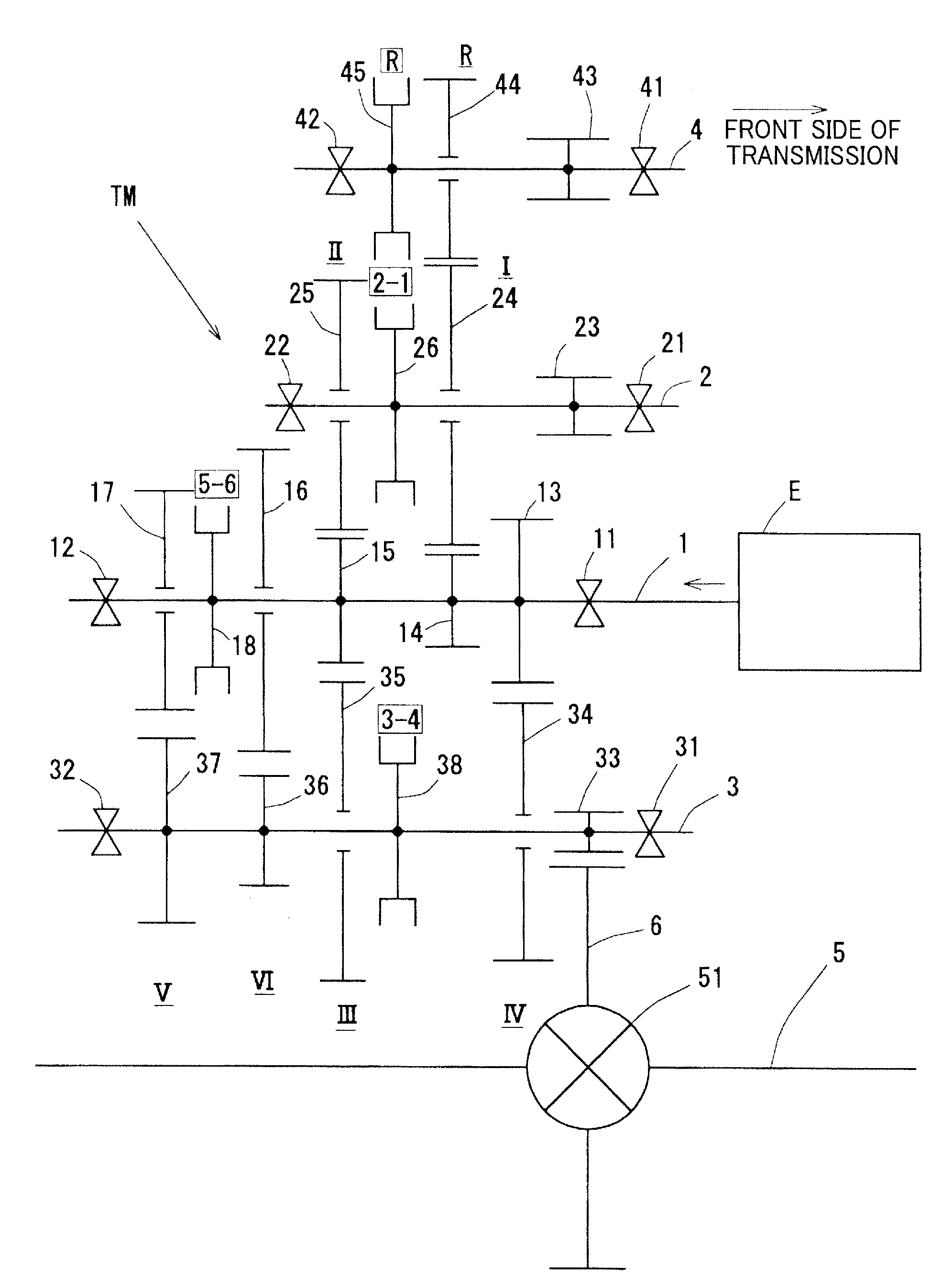
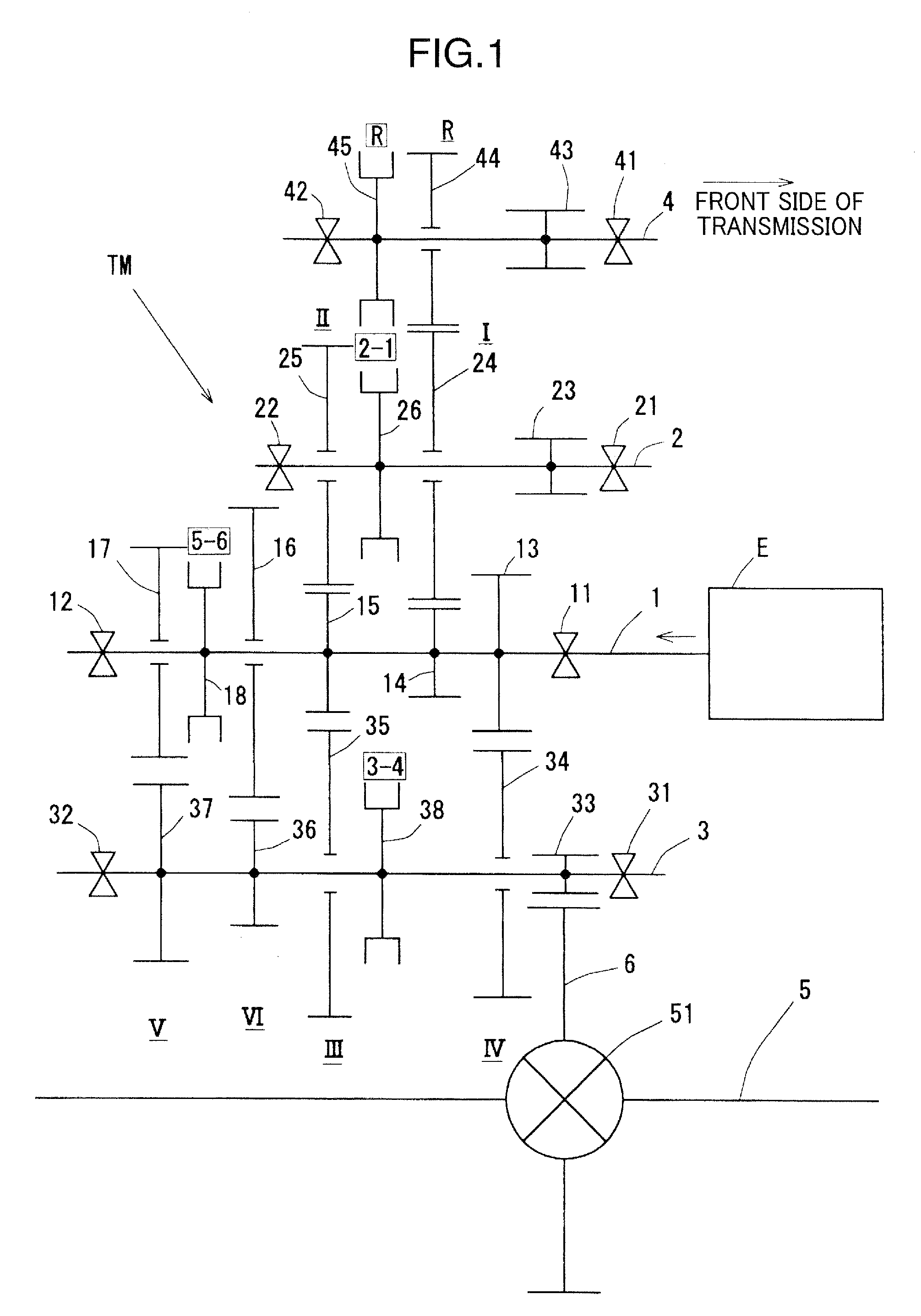
[0029]A geartrain of a transmission according to one embodiment of the present invention will be firstly described with reference to FIG. 1, which is a skeletal diagram showing the geartrain of the transmission. In the following description, a near side of the transmission with respect to an engine E will be referred to as ā€œfront or front sideā€ in terms of the transmission or any component of the transmission, and a far side of the transmission with respect to the engine E, i.e., a side of the transmission opposite to the near side, will be referred to as ā€œrear or rear sideā€ in terms of the transmission or any component of the transmissionā€.

[0030]The transmission TM according to this embodiment is a so-called ā€œtransverse manual transmissionā€ of a multi-shaft type having a plurality of shafts, which is designed to achieve six frontward speed stages and one reverse speed st...


PUM


Abstract

The present invention is directed to a transmission capable of minimizing the number of speed-change driven gears on a first countershaft to ensure a layout space in an engine compartment of a vehicle, and reducing a driving torque to be applied to a second countershaft to facilitate downsizing of the transmission. In the transmission, the first countershaft 2 is arranged at a position above an input shaft 1, and a first-speed driven gear 14 and a second-speed driven gear 24 are provided on the first countershaft 2.

Description

BACKGROUND OF THE INVENTION[0001]1. Field of the Invention[0002]The present invention relates to a transmission, and more particularly to a transmission designed to achieve six forward speed stages and one reverse speed stages, wherein an input shaft and an output shaft (countershaft) are disposed on respective different axes.[0003]2. Description of the Related Art[0004]Heretofore, as a transmission intended to be disposed on a lateral side of a transversely disposed engine (i.e., transverse engine), a so-called ā€œtransverse transmissionā€ has been commonly employed which is designed such that an input shaft and an output shaft (countershaft) are disposed in parallel on respective different axes, and a plurality of speed-change gear sets are disposed between the input shaft and the output shaft (countershaft).[0005]In view of improvement in drive feeling, there exists a strong need for the transverse transmission to further increase the number of speed stages, as with other types of t...

Claims


Application Information

Patent Timeline
04 Dec 2008
Publication
US20080295627A1
IPC
F16H3/08
CPC
F16H3/093; Y10T74/19233; F16H2200/0052; F16H2003/0931
Inventors
OKADOME, YASUKI; KUWAHARA, WATARU