

Pneumatic tire
Inactive Publication Date: 2008-12-04
SUMITOMO RUBBER IND LTD
View PDF5 Cites 21 Cited by
- Summary
- Abstract
- Description
- Claims
- Application Information
AI Technical Summary
Benefits of technology
[0017]The pneumatic tires of the present invention having a structure as mentioned above can reduce the electric resistance while suppressing the amount of carbon black as small as possible, and
Problems solved by technology
Further, as petroleum resources are limited and its supply is decreasing year by year, large increase in oil price in future is predicted.
Therefore, there is a limit to the use of raw materials derived from petroleum resources.
Consequently, it causes a problem that static electricity is accumulated in a vehicle to cause radio disturbance su
Method used
View moreImage
Smart ImageViewing Examples

Examples
 PUM
 Abstract
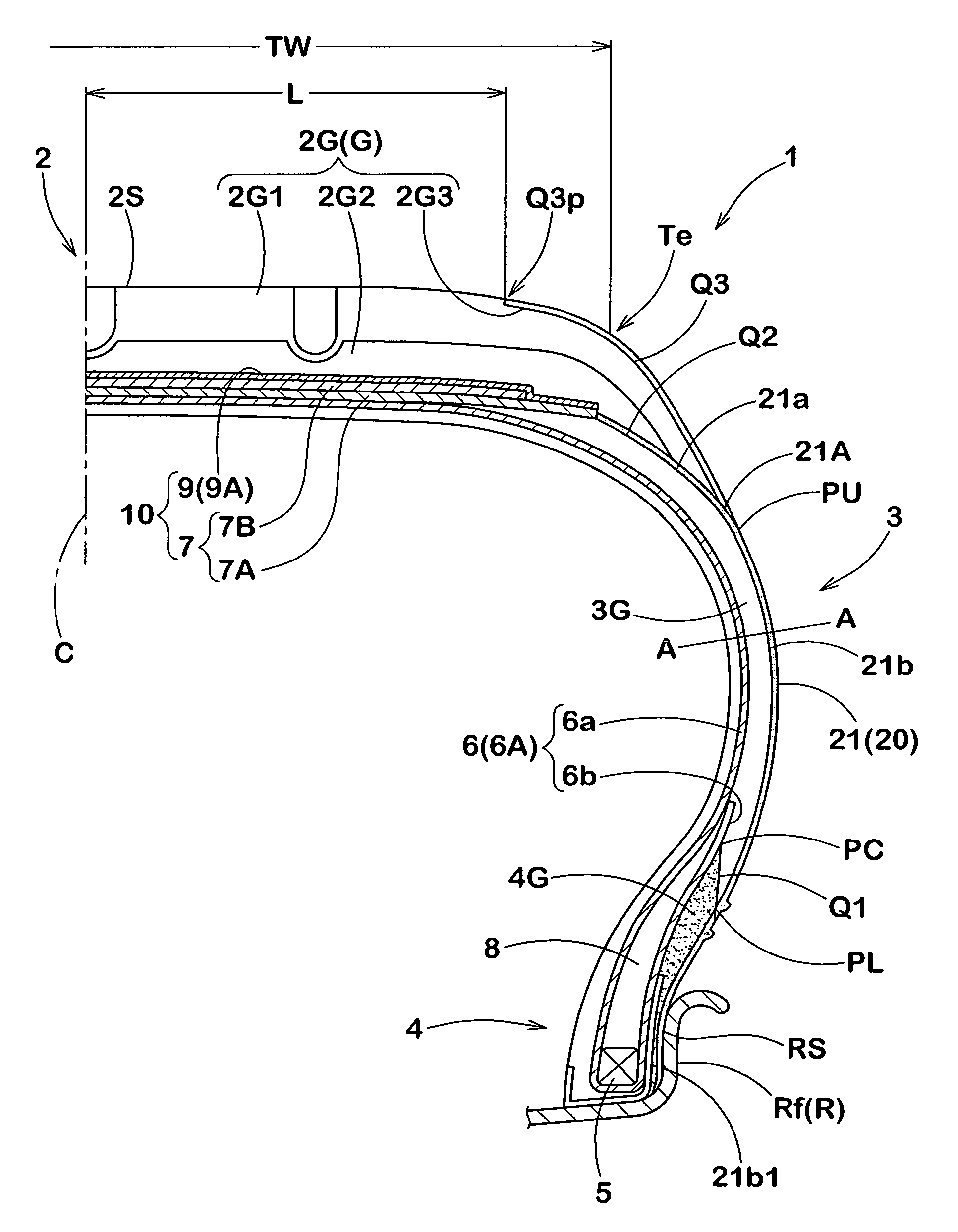
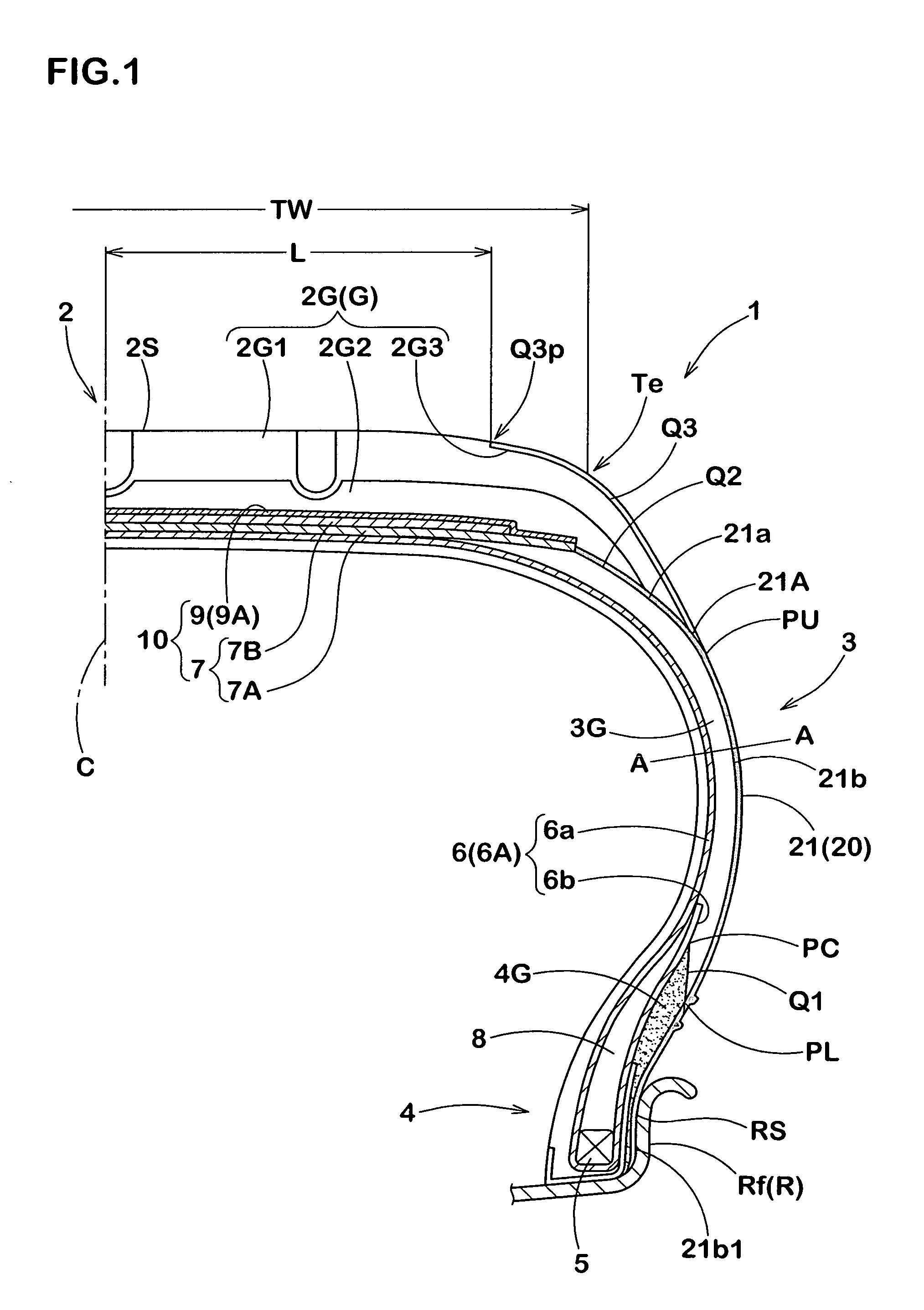
A pneumatic tire wherein at least 75% by weight of tire-constituting components based on the tire overall weight are made of nonpetroleum-based materials and wherein, at least, base rubber 2G2 and cap rubber 2G1 of tread rubber 2G, sidewall rubbers 3G and a topping rubber of carcass 6 are formed of an insulating rubber material, wing rubbers 2G3 of tread rubber 2G are formed of an electrically conductive rubber material, and sidewall portions are provided with at least one electrically conducting path 20 formed from a ribbon-like conductive rubber strip 21 made of an electrically conductive rubber material and having a width Ws of 10 to 40 mm, in which the conductive rubber strip 21 extends linearly in a radially inward direction from an electrically conducting part 21A contacting the wing rubber 2G3 to reach clinch rubber 4G.
Description
BACKGROUND OF THE INVENTION[0001]The present invention relates to a pneumatic tire capable of preventing electrostatic accumulation, more particularly to a pneumatic tire having in a sidewall portion an electrically conducting path formed by a ribbon-like electrically conductive rubber strip extending linearly in a radial direction.[0002]In tires currently put on the market, tire-constituting components occupying 50% or more of the overall weight of a tire are made of petroleum-based materials derived from petroleum as a raw material. For example, general radial tires for passenger cars contain about 20% by weight or more of a synthetic rubber, about 20% by weight or more of a carbon black, and others, e.g., a petroleum-based oil such as aromatic oil and a synthetic fiber, based on the overall tire weight.[0003]On the other hand, in recent years, CO2 emission regulation is tightened from the viewpoint of environmental problems. Further, as petroleum resources are limited and its sup...
Claims
Login to View More Application Information
Patent Timeline
 IPC IPC(8): B60C19/00
CPCB60C19/08
InventorMAFUNE, TOSHIYUKISAKAMOTO, MASAYUKINOBUCHIKA, HIDEO
OwnerSUMITOMO RUBBER IND LTD