
Connector

Inactive Publication Date: 2008-12-04
IRISO ELECTRONICS CO LTD
View PDF2 Cites 11 Cited by
  • Summary
  • Abstract
  • Description
  • Claims
  • Application Information

AI Technical Summary

Benefits of technology

[0010]According to the present invention, since the load generated in the second terminal by the elastic deformation of the first terminal can be reduced, connection reliability between the second terminal and the other object to be connected can be improved. Also, since the first and second terminals are elastically deformed, a movable range can be made larger and displacement between the one object to be connected and the other object to be connected is absorbed so as to facilitate electric connection.

Problems solved by technology

However, with this connector, since each of the second terminals held by the second fixed housing is fixed to the other object to be connected, if the second fixed housing is fitted with the movable housing while each of the first terminals is elastically deformed, a load in the fitting direction is generated in each of the second terminals by a restoring force of each of the first terminals, which might lower connection reliability between each of the second terminals and the other object to be connected.

Method used


Image

  • Connector
  • Connector
  • Connector

Examples


Embodiment Construction

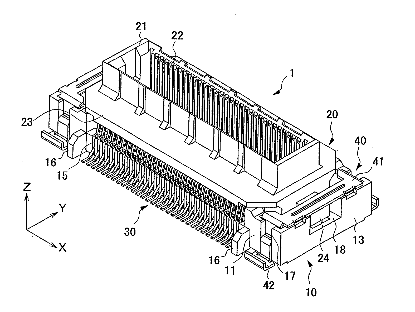
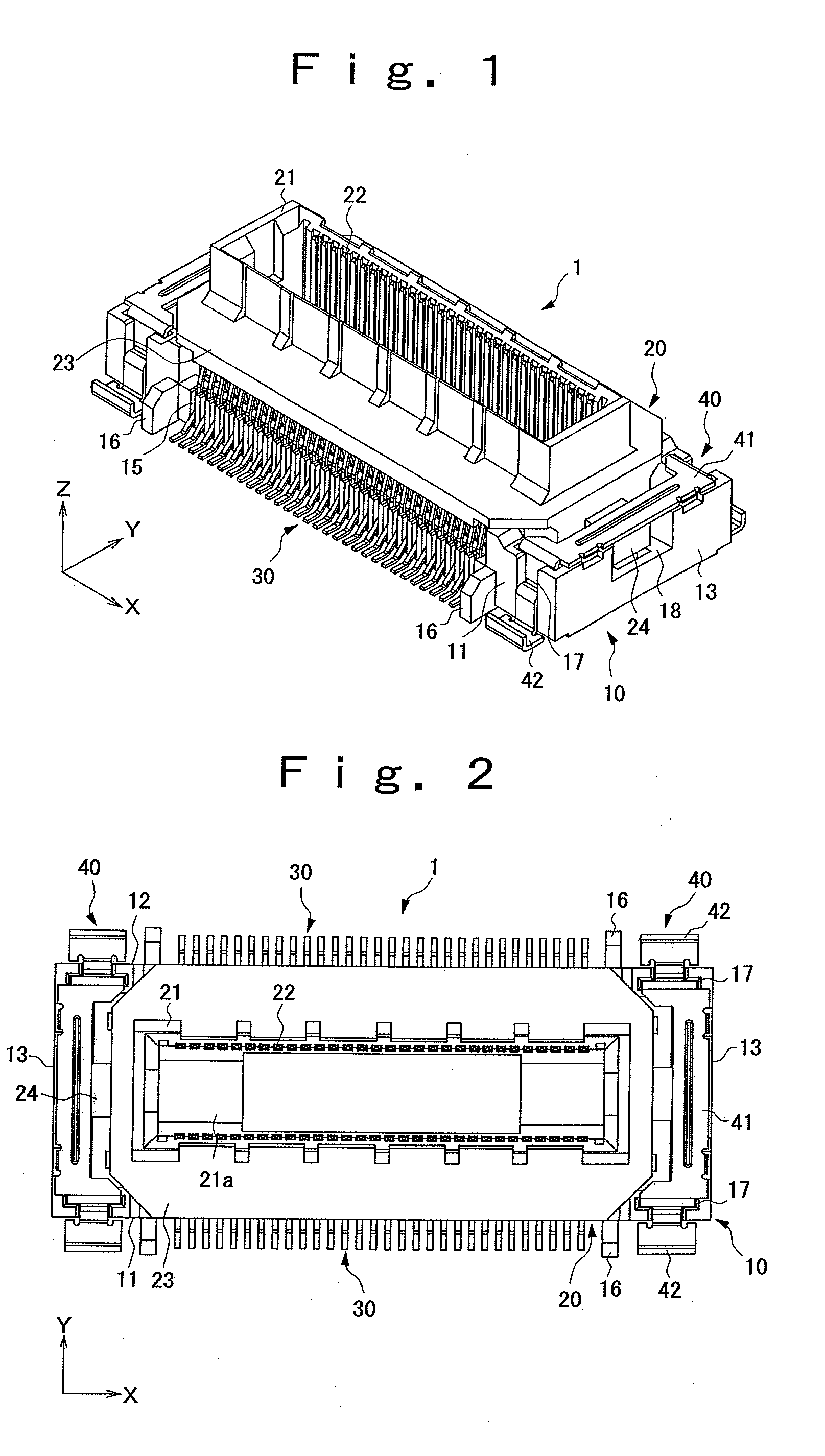
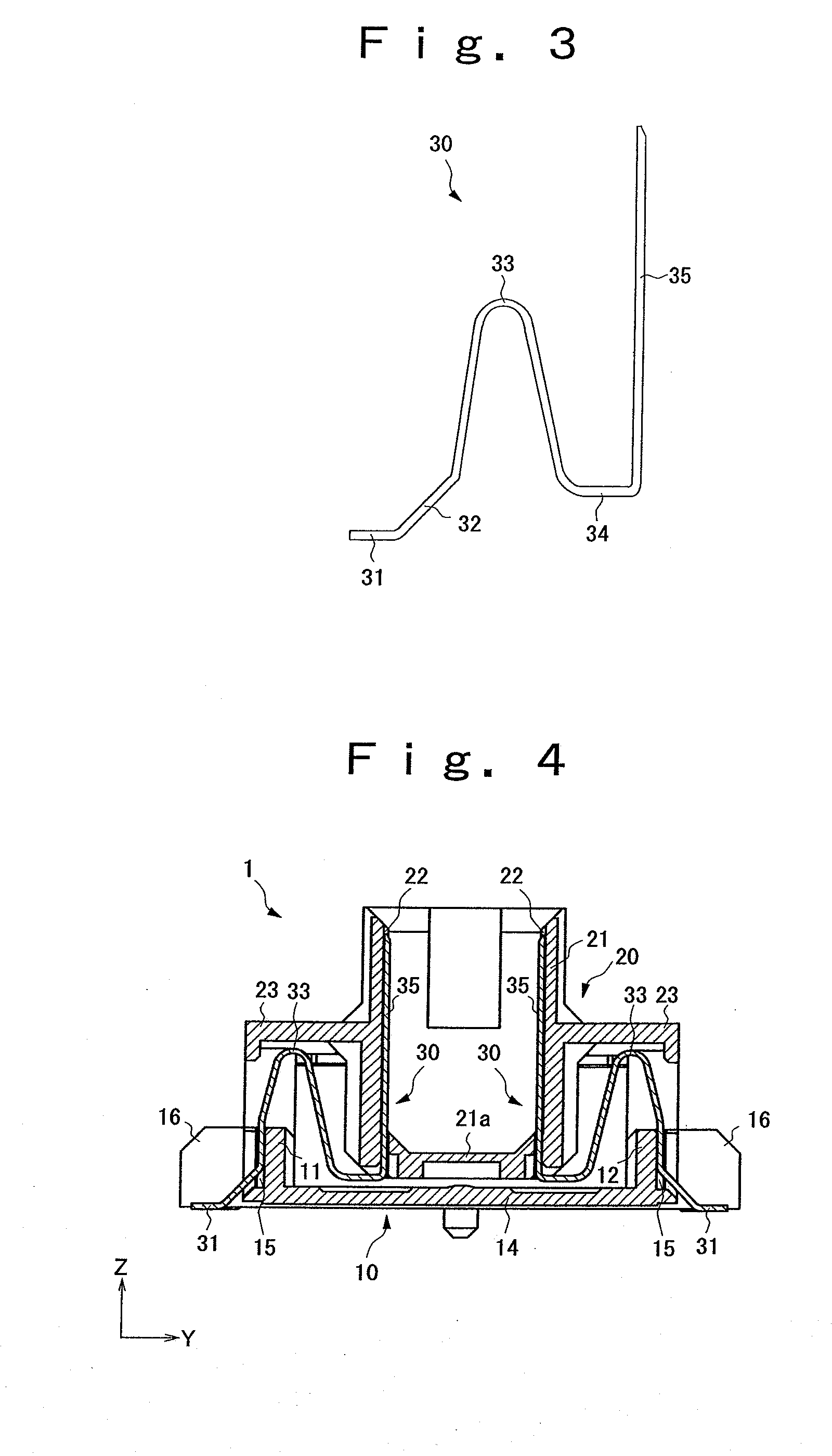
[0035]FIGS. 1 to 10 illustrate an embodiment of the present invention, in which FIG. 1 is a perspective view of a plug, FIG. 2 is a plan view of the plug, FIG. 3 is a side view of a plug terminal, FIG. 4 is a side sectional view of the plug, FIG. 5 is a perspective view of a socket, FIG. 6 is a plan view of the socket, FIG. 7 is a side view of a socket terminal, FIG. 8 is a side sectional view of the socket, and FIGS. 9 and 10 are side sectional view illustrating an operation when the plug and the socket are fitted together.

[0036]This connector comprises a plug 1 and a socket 2 and used for electrically connecting a first board 100 as one object to be connected which is connected to the plug 1 and a second board 200 as the other object to be connected which is connected to the socket 2.

[0037]At the plug 1, a first fixed housing 10 arranged on the side of the first board 100, a first movable housing 20 provided movably in a width direction (X direction in the figure), a front-and-rea...


PUM


Abstract

The present invention provides a connector that can reduce a load generated on a second terminal by elastic deformation of a first terminal. The connector comprises a first movable housing movable relative to a first stationary housing disposed on the side of a first substrate, multiple plug terminals elastically deformed as the first movable housing moves, a second movable housing movable relative to a second stationary housing disposed on the side of a second substrate, and multiple socket terminals that are elastically deformed as the second movable housing moves and that are contacted with the respective plug terminals when the second movable housing is fitted to the first movable housing, and therefore, a load generated on the socket terminals by the elastic deformation of the plug terminals can be reduced. Thus, connection reliability between the socket terminals and the second substrate can be improved.

Description

BACKGROUND OF THE INVENTION[0001]1. Field of the Invention[0002]The present invention relates to a connector mounted on a print circuit board and the like to be used for electrically connecting a plurality of circuit boards.[0003]2. Description of the Related Art[0004]As this type of connectors, a connector comprising a first fixed housing arranged on the side of one of objects to be connected, a movable housing provided movably with respect to the first fixed housing, a plurality of first terminals formed so that one end side is held by the fixed housing and the other end side is held by the movable housing and the terminal is elastically deformed with movement of the movable housing, a second fixed housing arranged on the side of the other of the objects to be connected and formed fittable to the movable housing, and a plurality of second terminals held by the second fixed housing and brought into contact with the other end side of each of the first terminals when the second fixed...

Claims


Application Information

Patent Timeline
IPC IPC(8): H01H9/00
CPCH01R13/6315H01R13/26H01R12/91H01R12/73H01R12/52
Inventor URA, TAKAHIRO
Owner IRISO ELECTRONICS CO LTD
Learn More