Sliding member

a sliding member and member technology, applied in the direction of sliding contact bearings, mechanical devices, transportation and packaging, etc., can solve the problems of cracking and cracking of the sliding layer surface, damage to the sliding layer, and the resin composition in the vicinity of the sliding surface is largely deformed,

Active Publication Date: 2020-10-06
DAIDO METAL CO LTD
View PDF22 Cites 3 Cited by
  • Summary
  • Abstract
  • Description
  • Claims
  • Application Information

AI Technical Summary

Benefits of technology

[0004]On the contrary, if a greater ratio of fibrous particles are orientated in the sliding layer such that a major axis thereof is directed parallel to the sliding layer, the elastic deformation of the resin composition in the rotation direction of the shaft member decreases. Even then, the damages of the sliding layer can not be completely prevented, and furthermore another problem is raised that shearing is easily generated at an interface between the back metal layer and the sliding layer.
[0005]Accordingly, an object of the present invention is to overcomes the above problems of the conventional technologies, and provide a sliding member that is hardly subjected to damages such as cracking on a surface of a sliding layer at a startup of a bearing device, and also to shearing between the sliding layer and a back metal layer.

Problems solved by technology

In the case, if the resin composition includes non-oriented or isotropically dispersed fibrous particles as disclosed in JP-A-2013-194204, the resin composition in the vicinity of the sliding surface is largely deformed, and damages such as cracking possibly occurs on the surface of the sliding layer.
Even then, the damages of the sliding layer can not be completely prevented, and furthermore another problem is raised that shearing is easily generated at an interface between the back metal layer and the sliding layer.

Method used


Image

  • Sliding member
  • Sliding member
  • Sliding member

Examples


examples

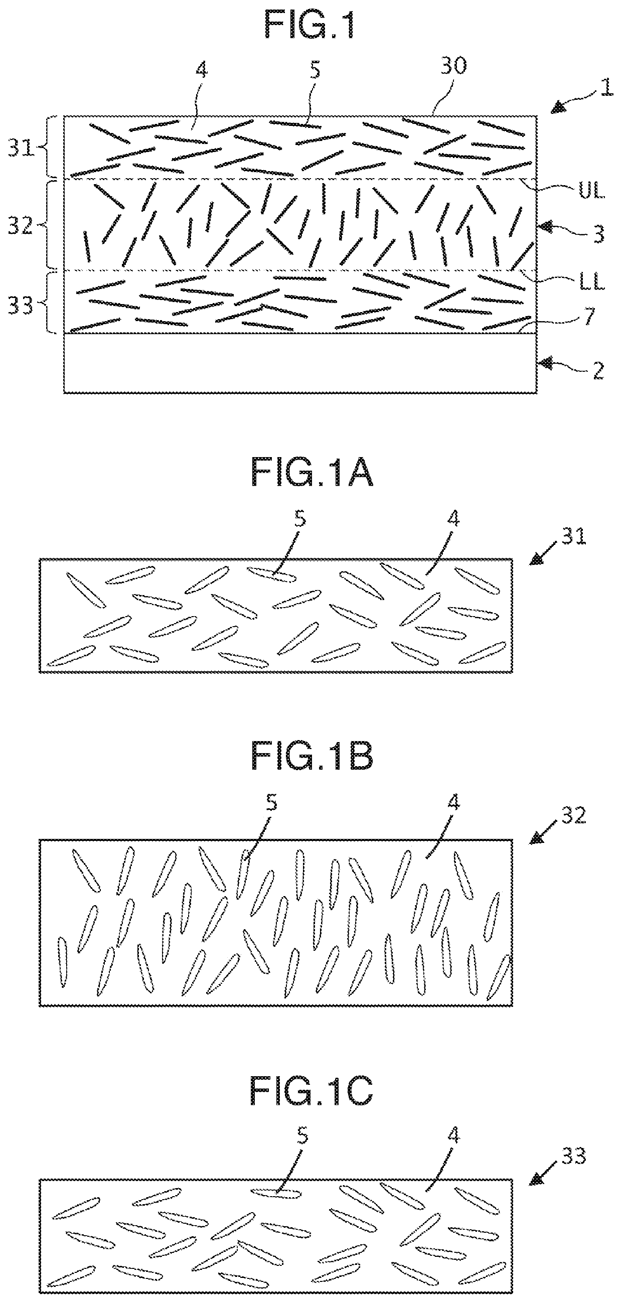
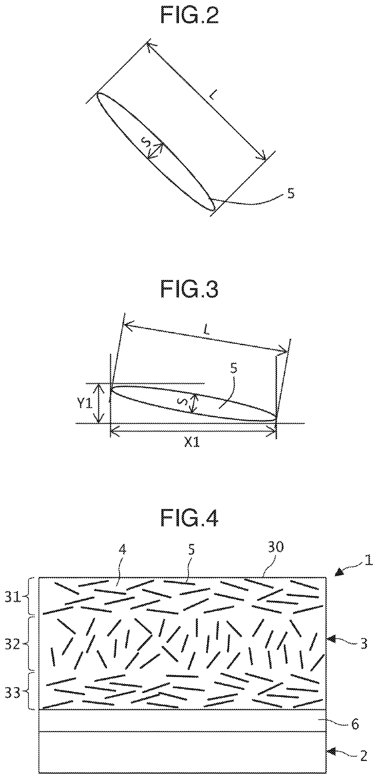
[0093]For the sliding members including a back metal layer and a sliding layer, Examples 1 to 10 according to the invention and Comparative Examples 11 to 17 were produced as follows. Table 1 shows compositions of sliding layer of sliding member of Examples 1 to 10 and Comparative Examples 11 to 17.

[0094]

TABLE 1Composition (volume %)Fibrous particleFibrous particleCross-AverageAverageSynthetic resinCarbonGlassSolid lubricantFillerlinkingparticleaspectSamplePEEKPFfiberfiberGrMoS2CaF2promotorsize (μm)ratio (A)Example190—10—————51.4of the280——20————253.2invention370—30—————103.8475—20———5—205.5570—25——5——226.2665—35—5—5—237.1760——20—10 10 —219.1870—15—5—10 —2010975——15—55—205.910—75—25————51.7Compar-1170——30————31.3ative1270——30————303.2Example1395— 5—————203.11460—40—————153.81570——30————153.41675—25—————253.317—7025————5103Fibrous particleDispersion index (S)EvaluationSliding surfaceIntermediateInterfaceVolumeShearing inAbrasionSampleside areaareaside arearatio (%)Crackinginterface(μ...


PUM

PropertyMeasurementUnit
particle sizeaaaaaaaaaa
lengthaaaaaaaaaa
aspect ratioaaaaaaaaaa

Abstract

Provided is a partially-cylindrical sliding member including a sliding layer including fibrous particles having an average particle size of 5-25 μm dispersed in a synthetic resin at a volume ratio of 10-35% of the sliding layer. The particles having a major axis length ≤20 μm are included at a volume ratio of ≥10% to total particles. A sliding surface side area is defined from the sliding surface and has a thickness of 25% of a sliding layer thickness T, where the fibrous particles having a major axis length of ≥20 μm have a dispersion index of 1.1-6. An interface side area is defined from the interface and has a thickness of 25% of T, where the dispersion index is 1.1-6. An intermediate area is defined between the both areas, where the dispersion index is 0.1 to less than 1.

Description

BACKGROUND OF THE INVENTIONField of the Invention[0001]The present invention relates to a sliding member for a journal bearing. Particularly, the invention relates to a sliding member having a partially cylindrical shape and including a back metal layer and a sliding layer including synthetic resin and fibrous particles. The invention further relates to a journal bearing including the sliding member.Description of the Related Art[0002]A radial bearing has been used as a journal bearing for a rotation shaft of an exhaust turbine, a large-scale electrical generator or other devices. The radial bearing includes a plurality of sliding members having a bearing pad shape with a circular-arc cross section, which are arranged a rotation shaft (see e.g. JP-A-2004-156690). As the sliding member for the radial bearing, a sliding member including a resin sliding layer coated on a back metal layer has been known. JP-A-10-204282 and JP-A-2016-079391 disclose a resin composition including fibrous ...

Claims


Application Information

Patent Timeline
Patent Type & Authority Patents(United States)
IPC IPC(8): F16C33/12F16C17/00F16C33/20B32B5/14B29C45/00F16C17/02
CPCF16C17/00F16C33/122F16C33/121F16C33/127F16C33/201F16C33/203F16C17/02F16C33/125B29C45/0005B32B5/145Y10T428/249946F16C2208/04F16C2208/20F16C2208/02F16C33/22F16C2220/08
Inventor YAMAUCHI, TAKAYOSHI
Owner DAIDO METAL CO LTD
Why Eureka
Try Eureka