Check Valve Device And Vapor Fuel Supply System

a technology of a check valve and a vapor fuel supply system, which is applied in the direction of combustion-air/fuel-air treatment, charge feed system, non-fuel substance addition to fuel, etc., can solve the problem of limited repeatability of impact stress on the valve portion, and achieve the effect of reducing the pressure difference, and reducing the decrease rate of pressure differen

Active Publication Date: 2017-02-02
HAMANAKODENSO
View PDF41 Cites 4 Cited by
  • Summary
  • Abstract
  • Description
  • Claims
  • Application Information

AI Technical Summary

Benefits of technology

[0005]It is an object of the present disclosure is to provide a check valve device or a vapor fuel supply system which is capable of improving durability of a valve portion.
[0006]According to an aspect of the present disclosure, a check valve device is capable of limiting a flow of a vapor fuel passing through a fluid passage in one direction. The check valve device includes a valve portion, an upstream passage forming member, a downstream passage forming member, and a narrowed passage. The valve portion extends radially outward from a valve shaft, and the valve portion is elastically deformable depending on a direction of a pressure of the vapor fuel. The valve portion is configured to prevent or allow a flow of the vapor fuel through the fluid passage by contacting with or separating from a valve seat located downstream of the fluid passage in accordance with an elastic deformation of the valve portion. The upstream passage forming member includes the fluid passage and the valve seat, and supports the valve shaft. The downstream passage forming member includes a terminal portion having therein a downstream passage through which the vapor fuel passed out of the fluid passage flows downstream. The downstream passage forming member is connected to the upstream passage forming member while the terminal portion is housed in the upstream passage forming member. The narrowed passage is provided inside the terminal portion or between an inner wall surface of the upstream passage forming member other than the valve seat and an outer circumferential surface of the terminal portion. A cross-sectional area of the narrowed passage is set to be smaller than any of the fluid passage and the downstream passage.
[0007]Accordingly, since the narrowed passage having the smaller cross-sectional area than any of the fluid passage and the downstream passage is located downstream of both the fluid passage and the valve portion, a drastic reduction in pressure difference between the fluid passage and the downstream passage can be restricted at a valve opening time when the valve portion is separated from the valve seat. The vapor fuel flowing out of the fluid passage at the valve opening time passes through the narrowed passage having the smaller cross-sectional area than the fluid passage. Thus, a pressure of in the fluid passage can be kept high relative to a pressure in the downstream passage. Accordingly, the pressure difference between the fluid passage and the downstream passage is maintained for a while, and the pressure difference can be reduced gradually. The reduction in decrease rate of the pressure difference can improve a condition of the valve portion such that the valve portion does not return drastically to its original shape via an elastic deformation toward the valve seat by a restoring force of the valve portion. Therefore, a frequency of alternate elastic deformations of the valve portion between valve closing and valve opening can be reduced, and thus repetition of impact stress on the valve portion can be limited. The check valve device capable of improving durability of the valve portion can be provided.

Problems solved by technology

Therefore, a frequency of alternate elastic deformations of the valve portion between valve closing and valve opening can be reduced, and thus repetition of impact stress on the valve portion can be limited.

Method used


Image

  • Check Valve Device And Vapor Fuel Supply System
  • Check Valve Device And Vapor Fuel Supply System
  • Check Valve Device And Vapor Fuel Supply System

Examples


first embodiment

[0025]A check valve device according to a first embodiment of the present disclosure and a vapor fuel supply system including the check valve will be described referring to FIGS. 1 to 6.

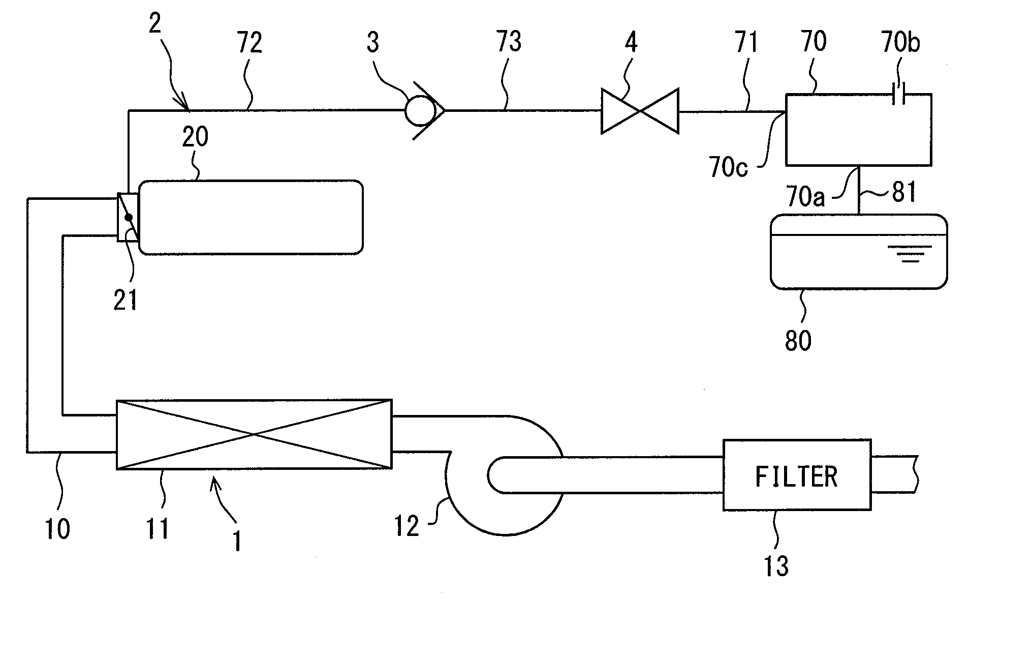
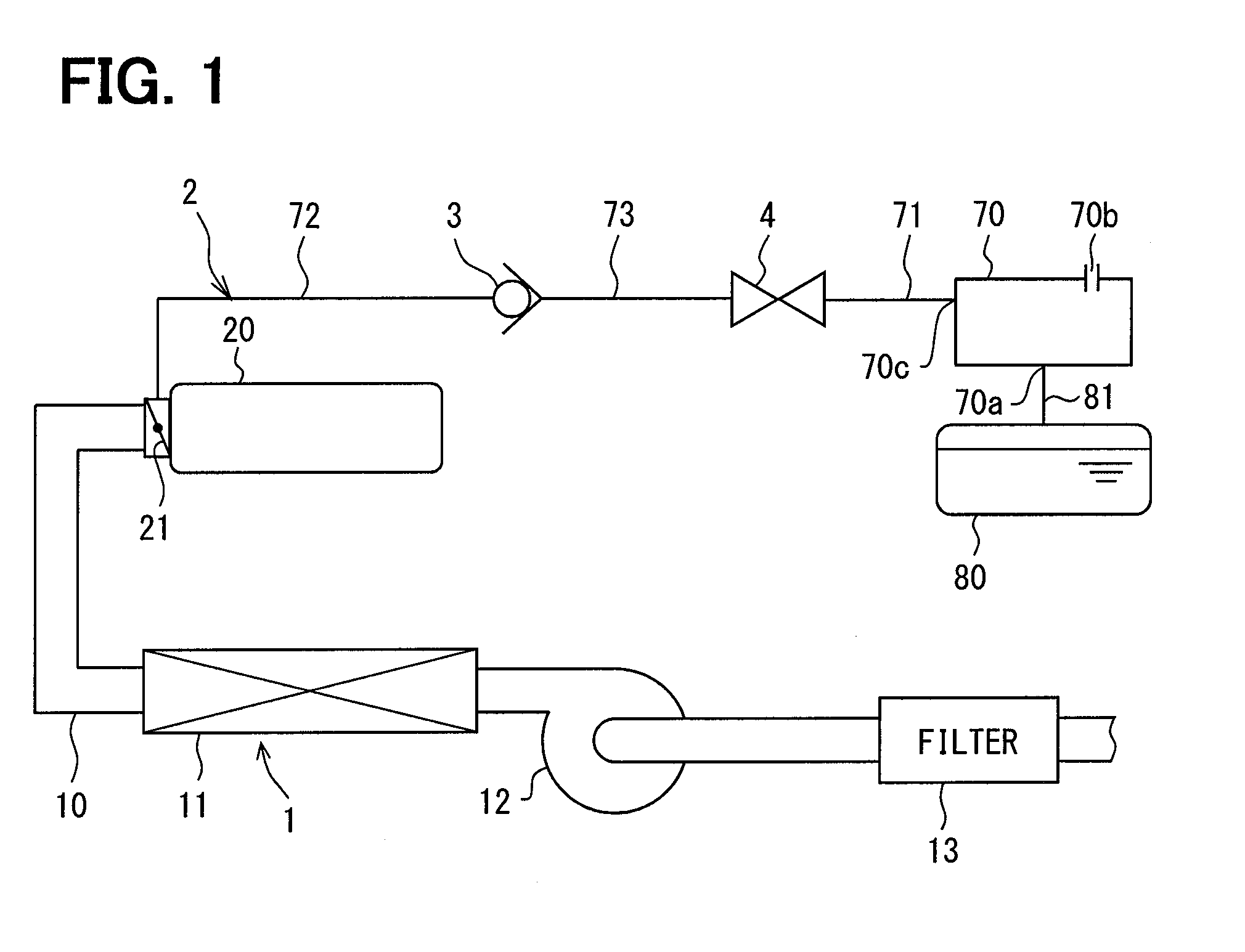
[0026]A vapor fuel introduced into an intake system 1 of an engine is mixed with a combustion fuel supplied from an injector or the like to the engine. The vapor fuel mixed with the combustion fuel is combusted in an cylinder of the engine. The intake system 1 of the engine includes an intake pipe 10 having one end side connected to an intake manifold 20 of the engine through a throttle valve 21. The intake system 1 is configured by providing a filter 13, a turbocharger 12 and an intercooler 11 in the intake pipe 10. A vapor fuel purge system 2 is configured by connecting a fuel tank 80 and a canister 70 to the intake manifold 20 through a pipe 81, a pipe 71 and a pipe 72.

[0027]The filter 13 is located on the most upstream part of the intake pipe 10 and traps dust contained in an intake air. The turb...

second embodiment

[0068]In a second embodiment, a check valve device 103 will be described as a modification of the check valve device 3 of the first embodiment with reference to FIGS. 7 to 9. In each figure, a part having the same configuration as the first embodiment will be assigned the same numeral and exerts the same actions and effects. The configurations, actions or effects which are not mentioned particularly in the second embodiment are the same as the first embodiment. Only different points from the first embodiment will be described below. The part in the second embodiment which has a similar configuration to the first embodiment is considered to exert the similar actions and effects to the first embedment. The check valve device 103 can be used for the fuel vapor supply system of the first embodiment.

[0069]FIG. 7 is a sectional diagram showing the check valve device 103 when the check valve device 103 is closed. FIG. 8 is a sectional diagram showing the check valve device 103 when the che...

third embodiment

[0073]In a third embodiment, a check valve device 203 will be described as a modification of the check valve device 3 of the first embodiment with reference to FIGS. 10 and 11. In FIGS. 10 and 11, a part having the same configuration as the first embodiment will be assigned the same numeral and exerts the same actions and effects. The configurations, actions or effects which are not mentioned particularly in the third embodiment are the same as the first embodiment. Only different points from the first embodiment will be described below. The part in the third embodiment which has a similar configuration to the first embodiment is considered to exert the similar actions and effects to the first embedment. The check valve device 203 can be used for the fuel vapor supply system of the first embodiment.

[0074]FIG. 10 is a sectional diagram showing the check valve device 203 when the check valve device 203 is closed. FIG. 11 is a sectional diagram showing the check valve device 203 when t...


PUM


Abstract

A check valve device includes a valve portion elastically deformable to prevent or allow a flow of a vapor fuel through a fluid passage in one direction by contacting with or separating from a valve seat. An upstream passage forming member has the valve seat and the fluid passage located upstream of the valve portion. A downstream passage forming member includes a terminal portion housed in the upstream passage forming member and having a downstream passage. A narrowed passage provided inside the terminal portion or between the upstream passage forming member and the terminal portion. A cross-sectional area of the narrowed passage is set to be smaller than any of the fluid passage and the downstream passage.

Description

CROSS REFERENCE TO RELATED APPLICATION[0001]This application is based on and incorporates herein by reference Japanese Patent Application No. 2015-148071 filed on Jul. 27, 2015.TECHNICAL FIELD[0002]The present disclosure relates to a check valve device used for a system which supplies a vapor fuel from a canister to an intake pipe in an automobile, and relates to a vapor fuel supply system including the check valve device.BACKGROUND[0003]As an example of a conventional check valve device, a device disclosed by Patent Document 1 (JP 2005-172206 A corresponding to US 2005-0126649 A1) is known. The check valve device of Patent Document 1 obtains a sealing effect by line contact between an outer circumferential rim of an upstream side of a sealing part of a rubber valving element and a circular edge of a partition wall, and prevents a backward flow. The valving element is a component in which a valve portion having the umbrella-shaped sealing part and a shaft portion extending perpendic...

Claims


Application Information

Patent Timeline
Patent Type & Authority Applications(United States)
IPC IPC(8): F02M25/08F02M35/10F02M35/104F02M35/024
CPCF02M25/0836F02M25/0854F02M35/104F02M35/10157F02M35/10268F02M35/024F02M37/0023
Inventor FUJISAKI, YOSHIHIKO
Owner HAMANAKODENSO
Why Eureka
Try Eureka