Reverse Osmosis Filtration Devices with Rfid Tag-Powered Flow and Conductivity Meters

Active Publication Date: 2008-12-04
NITTO DENKO CORP +1
View PDF62 Cites 33 Cited by
  • Summary
  • Abstract
  • Description
  • Claims
  • Application Information

AI Technical Summary

Benefits of technology

[0032]In a further embodiment, the preloaded value and the measured value are transferred to the data retrieval device via communication with the RFID tag, and the data retrieval device is configured to use the preloaded value and the measured value to calculate a value indicative of the performance of the membrane filter device.
[0033]An embodiment of a method for monitoring performance of a membrane filter device is provide

Problems solved by technology

The calculated permeate conductivity of individual elements is only approximate and frequently incorrect mainly due to an inability to measure permeate flow at the point of water sample collection inside of the permeate tube.
Such a procedure i

Method used


Image

  • Reverse Osmosis Filtration Devices with Rfid Tag-Powered Flow and Conductivity Meters
  • Reverse Osmosis Filtration Devices with Rfid Tag-Powered Flow and Conductivity Meters
  • Reverse Osmosis Filtration Devices with Rfid Tag-Powered Flow and Conductivity Meters

Examples


Embodiment Construction

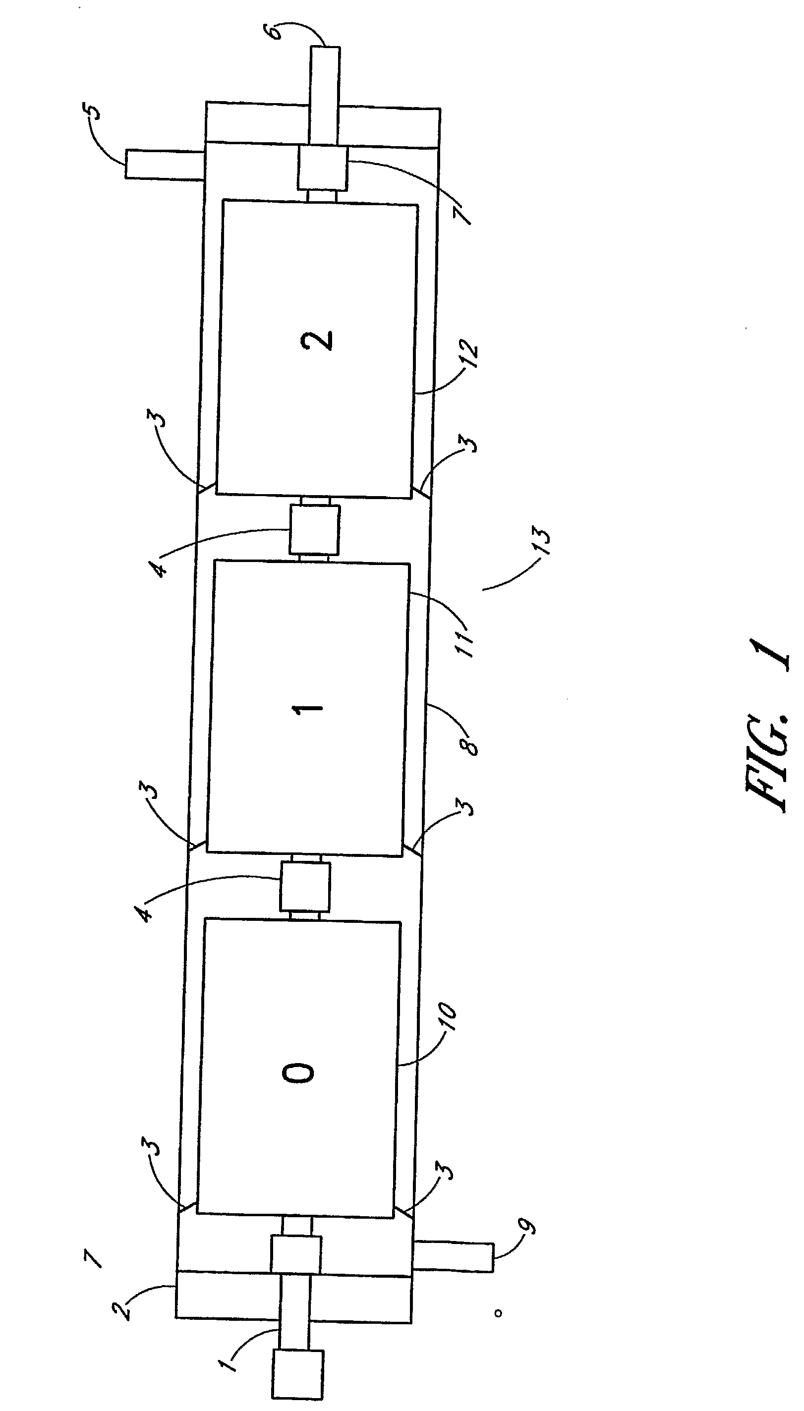
[0054]Embodiments of the present invention comprise reverse osmosis filters and systems comprising measuring devices. Real time measurements of salinity and permeate flow of individual filter devices, during reverse osmosis operations, provide many benefits over prior art methods of “probing” of the pressure vessels.

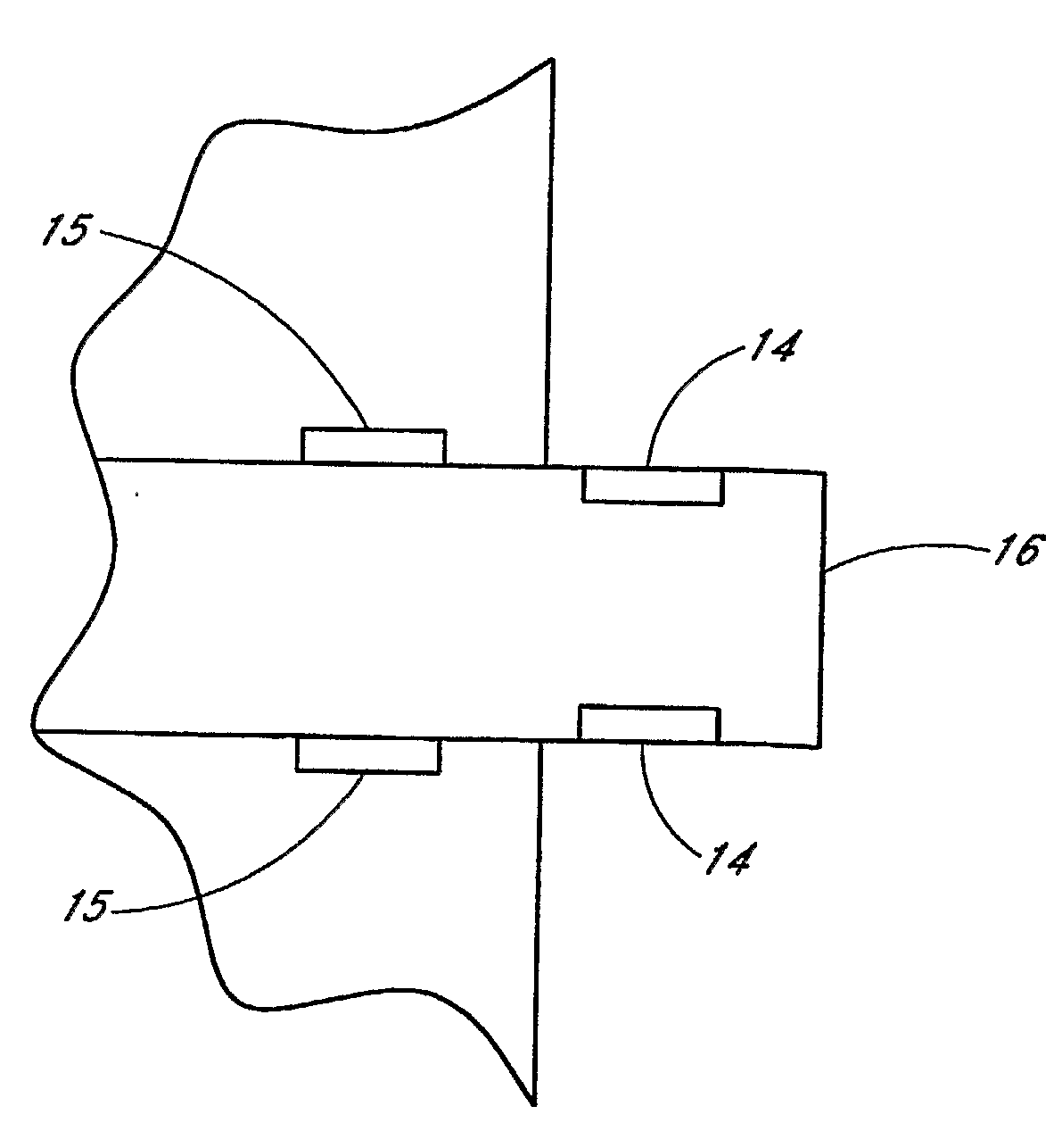
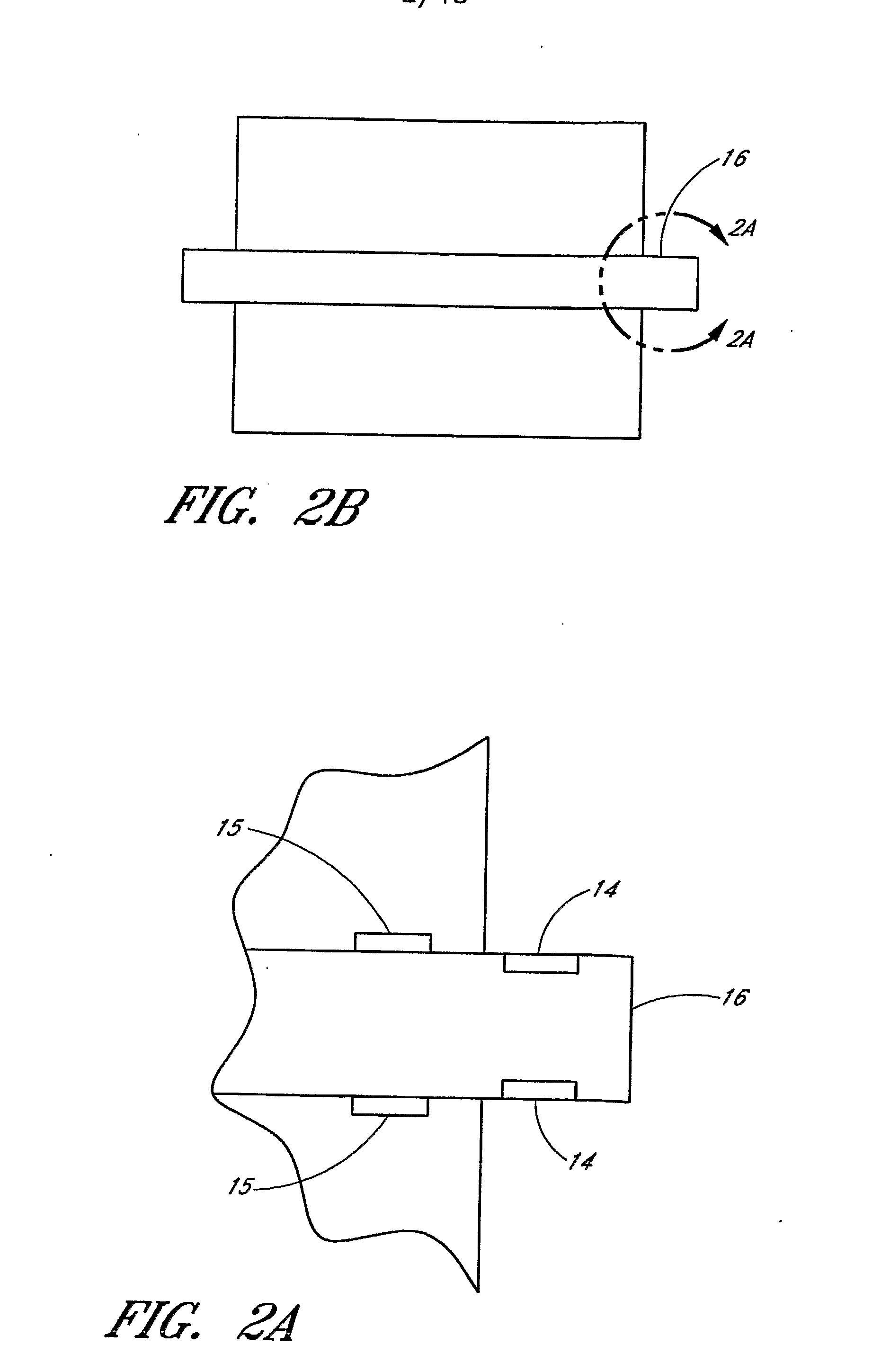
[0055]Such measuring devices preferably include, but are not limited to, fluid flow meters and fluid conductivity meters. The flow meters of the present invention are preferably located outside of the permeate core tubes and connecting tubes of filtration devices and systems. Electromagnetic flow meters are preferably used to measure the flow rate of fluids. Alternate embodiments of the flow meters comprise rotatable members. Other embodiments of the flow meters comprise stress or strain gauges. Further embodiments comprise ultrasonic flow meters. The conductivity meters preferably comprise electrodes located within the permeate core tubes and connecting tubes of filtrat...


PUM

PropertyMeasurementUnit
Electrical conductivityaaaaaaaaaa
Flow rateaaaaaaaaaa
Energyaaaaaaaaaa

Abstract

The present invention relates to reverse osmosis filtration devices, and more particularly, to membrane filtration devices (10, 11, 12) that have flow meters and fluid conductivity meters powered by RFID tags. Embodiments of the present invention comprise reverse osmosis filters and filtration systems comprising measuring devices, including flow and conductivity meters. The meters of the present invention are preferably located on or within permeate core tubes (16) of filtration devices and systems.

Description

RELATED APPLICATIONS[0001]This application claims the benefit under 35 U.S.C. § 119(e) of U.S. Provisional Application No. 60 / 714,982, filed Sep. 7, 2005, the entirety of which is hereby incorporated by reference herein.BACKGROUND OF THE INVENTION[0002]1. Field of the Invention[0003]The present invention relates to reverse osmosis filtration devices, and more particularly, to filtration devices that have flow meters and fluid conductivity meters powered by RFID tags.[0004]2. Description of the Related Art[0005]Reverse osmosis (“RO”) filtration systems typically utilize spiral wound membrane filters. Spiral systems are usually staged with three to eight membrane filter devices connected in series within a pressure tube. The filter devices are connected through adapters on permeate tubes. The permeate from each filter device is combined together as a composite solution in the central tube of subsequent filter devices, connected in series, along the pressure vessel. A permeate in each ...

Claims


Application Information

Patent Timeline
IPC IPC(8): B01D35/143G01R27/08
CPCB01D61/025B01D61/12B01D63/10B01D63/12B01D2311/16B01D2311/243B01D2311/2607B01D2313/36C02F1/441C02F2209/05C02F2209/40
Inventor IKEYAMA, NORIOWILF, MARK
Owner NITTO DENKO CORP
Why Eureka
Try Eureka