Yarn Braking Device

a braking device and a technology of a cylinder head are applied in the field of cylinder head braking device, which can solve the problems of uneven development of force, limited adjustment range of braking effect, and inability to adjust the braking

Inactive Publication Date: 2008-12-04
IRO AB
View PDF2 Cites 10 Cited by
  • Summary
  • Abstract
  • Description
  • Claims
  • Application Information

AI Technical Summary

Benefits of technology

[0008]In accordance with the first embodiment, the pair of the permanent magnets operates without contact and with a function which is not liable to aging, to aggressive substances, to misalignments, does not tend to develop the force irregularly, and which assures a wide adjustment range for the braking effect. The pair of permanent magnets exclusively has to generate the resilient axial force which determines the braking effect while the needed centering of the frustocone coat braking body is carried out at the small diameter end section by the sliding guiding system. The produced centering effect is the same for all adjustments of the braking effect. Both functions, i.e. the generation of the axial resilient force and the axial guidance may by optimised respectively per se since these functions do not interfere with each other during the operation of the yarn braking device. The problem of lint collection and the negative influence of collected lint are eliminated. The structural construction of the yarn braking device is simple and results in high reliability as there are no liable mechanical spring components.
[0025]In a further expedient embodiment an essentially cylindrical extension is provided at the support ring body. The cylindrical extension extends through the carrying ring of the support cage without contacting the carrying ring. This measure stiffens the support ring body and allows to limit the displacement of the braking body in an emergency case under extreme sideward displacement. During normal operation of the yarn braking device, however, there will not be any contact between the extension and the carrying ring.

Problems solved by technology

A general problem of mechanical springs is a development of the force which is not uniform in circumferential direction, the susceptibility to aggressive substances, and a tendency to collect lint.
A further problem is that the mechanical spring at the same time has to centre in radial direction and has to transmit the axial force on the braking body.
The adjustment range of the braking effect is limited by the nature of the mechanical spring, meaning that the mechanical spring has to be substituted by another as soon as a significant variation of the braking effect is needed.
In the case of a very weak braking effect due to the low spring load the centering and automatic return of the dislocated braking body into the centered position may fail, while in the case of an extremely strong adjustment of the braking effect the centering may be too rigid due to the high spring load.
Already small misalignments results in permanent fluctuations of the braking effect and in undesirable variations of the yarn tension.
However, due to the only linearly passing yarn the functional requirements for centering are low since the discs are centered mechanically and are inclined in relation to each other during operation.

Method used


Image

  • Yarn Braking Device
  • Yarn Braking Device
  • Yarn Braking Device

Examples


Embodiment Construction

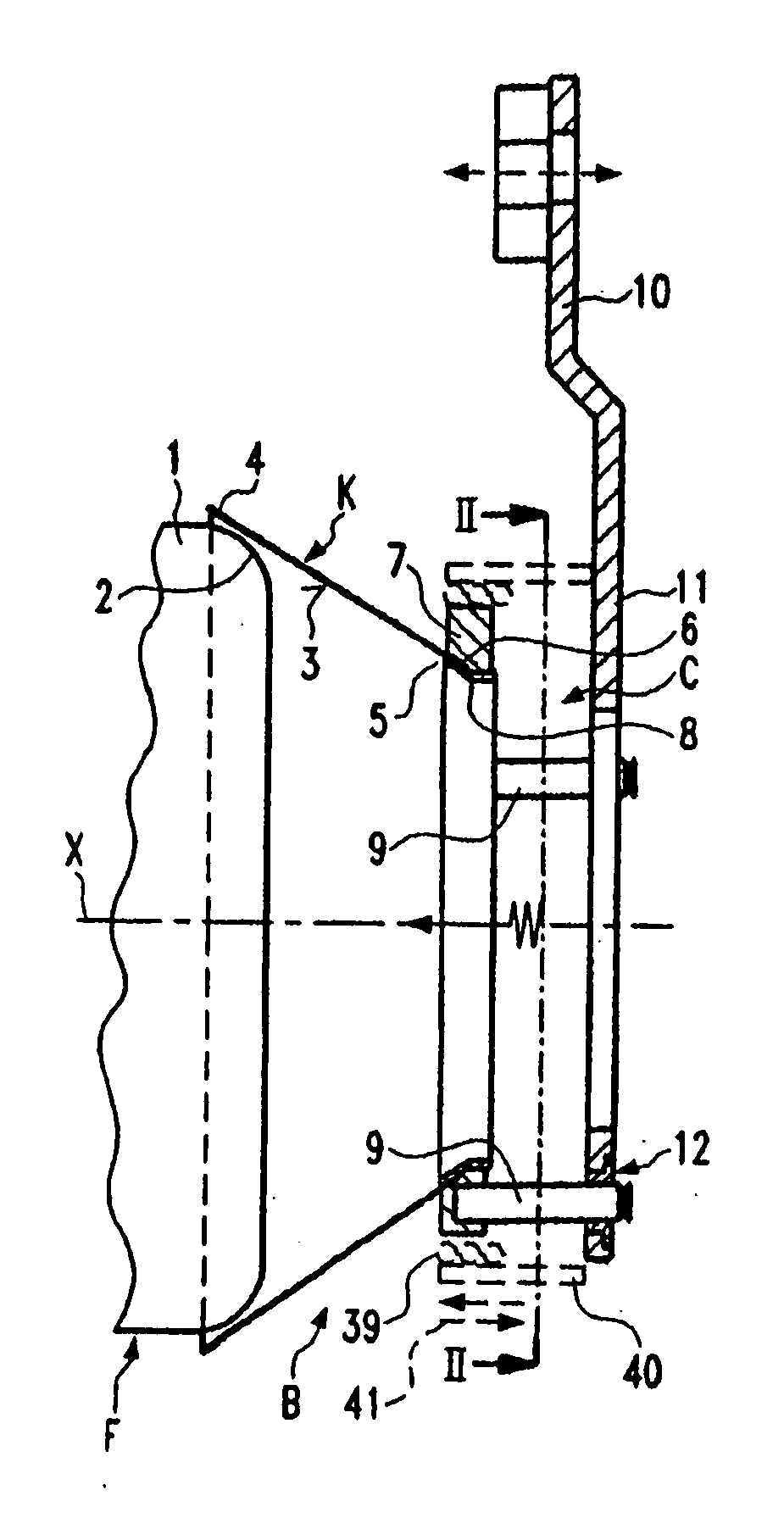
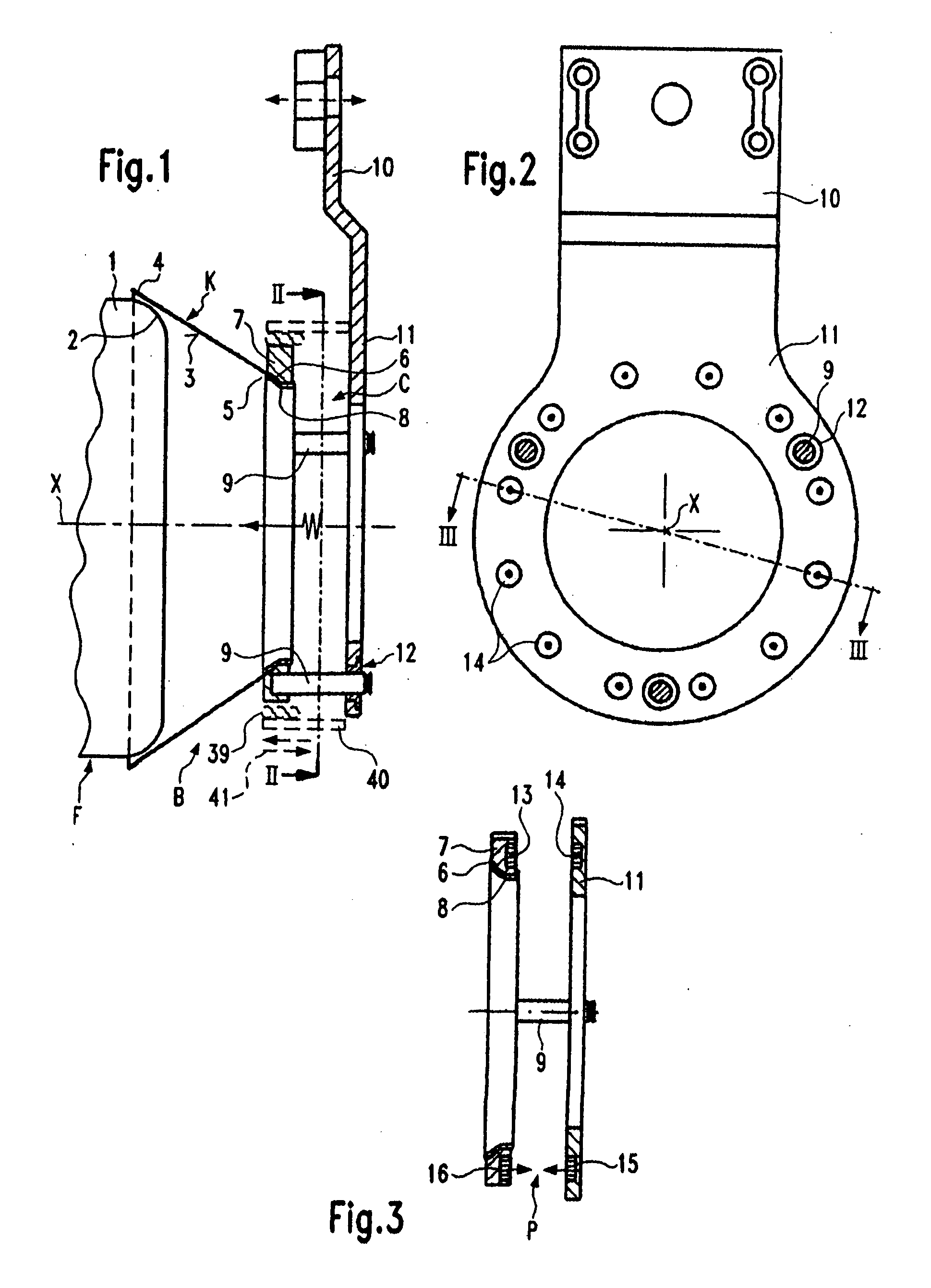
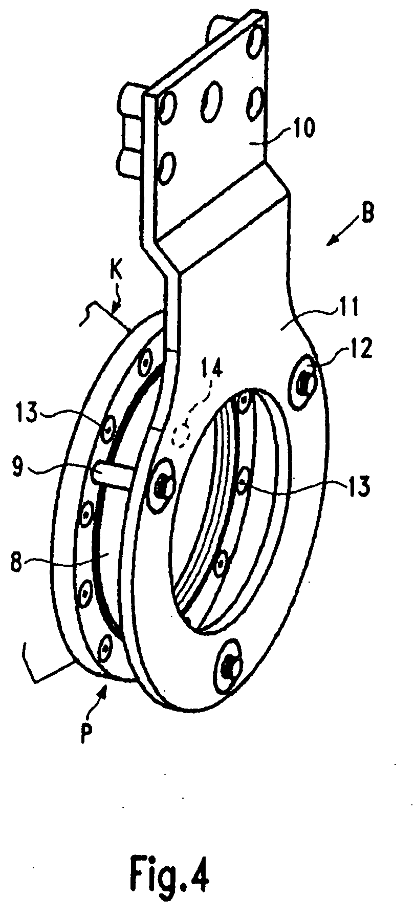
[0050]A first embodiment of a non-controlled yarn braking device B, shown in FIG. 4 in a perspective view, is explained with the help of FIGS. 1 to 4. The yarn braking device B is mounted in a yarn feeding device F (FIG. 1) comprising a drum-shaped stationary storage body 1 having a rounded withdrawal end 2 and an axis X which is also the axis of the yarn braking device B. A braking body K with the form of a frustocone coat 3 (having a straight line as a generatrice) is provided in the yarn braking device B. The braking body K is put with the large diameter end 4 over the withdrawal end 2 and is pressed against the withdrawal end 2 by an axially resilient force. The axially resilient force defines the braking effect for the yarn in the contact region between the inner side of the frustocone coat 3 and the withdrawal end 2. During the withdrawal and the run through the yarn braking device the withdrawn yarn is circulating like the hand of a clock. The braking body K e.g. is made from...


PUM


Abstract

The invention relates to a yarn tensioning device (B) comprising a braking body (K) embodied in the form of a truncated conical jacket (3) which is coaxially positioned on the rounded discharge end (2) of a storage body (1) and is pushed to a small diameter end (5) by the elastic axial force defining a braking effect between the braking body and the discharge end (2), an axial force generator (P) disposed between a fixed holding element (10) and the braking body and a centering device (C) provided with a radial working direction and disposed between the holding element (10) and the braking body, wherein said axial force generator (P) consists of at least one pair of axially superimposed permanent magnets, an intermediate slit is arranged between said permanent magnets and the centering device (C) which is embodied in the form of a axial slide guideway (9, 12, 24, 23) which is structurally and functionally separated from the permanent magnet pair or contactlessly formed thereby.

Description

FIELD OF THE INVENTION[0001]The invention relates to a yarn braking device.BACKGROUND OF THE INVENTION[0002]In a known yarn braking device (EP 0 534 263 A) a mechanical spring constitutes both the axial force generator and the radial centering device. The spring may be an annular radially oriented diaphragm, a radial spiral spring, a conical spiral spring, a cylindrical bellows, or, as shown in FIG. 1 of EP 0 652 312 A, a star-shaped spring arrangement consisting of helical tension springs each of which is hooked into the holder and into the support ring body, respectively. A general problem of mechanical springs is a development of the force which is not uniform in circumferential direction, the susceptibility to aggressive substances, and a tendency to collect lint. A further problem is that the mechanical spring at the same time has to centre in radial direction and has to transmit the axial force on the braking body. This dual function means a compromise between the development ...

Claims


Application Information

Patent Timeline
Patent Type & Authority Applications(United States)
IPC IPC(8): B65H59/22
CPCD03D47/34D03D47/366
Inventor COMOTTO, RENATOJACOBSSON, KURT ARNE GUNNAR
Owner IRO AB
Why Eureka
Try Eureka